
Q: What is a Doppler? What is a Roanoke Doppler?
A: Nineteenth Century physicist Christian Doppler is credited with creating equations that describe the apparent frequency shifts that result from the relative motion of the sender and receiver of a wave. The Doppler principle is now used for many applications, including dating the universe and catching highway speeders. In radio direction finding, a simulated rotating antenna can be used to determine the direction of an incoming signal using this principle.
When transmitter hunters speak of Dopplers, they usually mean a device with an electronically rotating array of 3 to 8 vertically oriented whips or dipoles and a circular display of 8 to 50 light-emitting diodes. These Doppler add-ons work with VHF and UHF narrowband FM receivers. There are other RDF devices with similar antenna sets and displays that are used with AM receivers (e.g Watson-Watt), but these are not Doppler sets. My six-part deep dive into Doppler technology is now in this Homing In site.
The Roanoke Doppler was first published in my book "TRANSMITTER HUNTING---Radio Direction Finding Simplified" (THRDFS), along with an extensive writeup of the theory of operation. After that publication, the Roanoke Doppler became the most popular Doppler RDF home construction project for many years. Originated by Chuck Tavaris N4FQ, then improved and documented by Joe Moell KØOV and Thomas Curlee WB6UZZ, the design was named by KØOV to honor the transmitter hunters of Roanoke, Virginia, where N4FQ tested his prototype. This Homing In site is the official support site of the Roanoke Doppler project:
There are other home-construction Doppler projects, but only the ones built from the design in THRDFS and this Web site are Roanoke Dopplers.
Q: I can't locate any 75492 ICs for the Roanoke Doppler display. What shall I do?
A: An improved 16-LED display circuit is in the THRDFS Update page at this site. The 75492 ICs have been eliminated. If you already have a circuit board for this project, you can still use it.
Q: The WA2EBY Doppler circuit in QST Magazine looks very much like the Roanoke Doppler. Is it an improvement?
A: That author has utilized many of the design attributes of the Roanoke Doppler, but his unit has no new functions or operating features.
Q: The WA2EBY article states that ECG-555 PIN diodes give poor UHF performance and that ordinary 1N4148 diodes are just as good for a Doppler antenna. Is that true?
A: First, The ECG-555 is an older PIN diode, with unspecified RF series resistance. Newer PIN diode types listed on the Hardware Sources page of this site should perform better. Second, the switcher circuit of the WA2EBY Doppler is not optimized for PIN diodes. For best isolation, RF diodes should be reverse-biased when OFF, not just at zero DC current. That's because the series capacitance of PIN diodes drops dramatically as OFF (reverse) bias goes from 0 to 4 volts. (Examples: HP 5082-3080 goes from 1.1 to 0.4 pF. MPN3404 goes from 2.5 to 1.4 pF.) The lower the capacitance, the less RF gets through (better isolation). The Wide-Range Roanoke Antenna at this Homing In site reverse-biases the OFF diodes, which is an important reason why it performs better than the original Roanoke antenna. The WA2EBY Doppler circuit does not reverse-bias the OFF diodes. I believe that the results of the WA2EBY's loss/isolation tests would have been quite different if it did.
I discuss PIN versus switching/rectifier diodes for Dopplers on page 128 of THRDFS. PIN diodes provide significantly less insertion loss when ON, if biased properly, meaning that a PIN switcher will generally have less loss. More importantly, stray RF rectification is much less likely with PINs. I encountered significant cross-modulation problems using a Doppler with non-PINs, especially when driving near strong RF sources. WA2EBY did not test for cross-modulation when he evaluated diodes. I would welcome input from anyone who has done such tests.
Q: Will the Roanoke Doppler find aircraft Emergency Locator Transmitters (ELTs)?
A: The Roanoke and other ring-antenna Doppler RDF sets can readily track signals in the 120 and 240 MHz aircraft bands, provided that a suitable receiver is used. The Doppler modulation produced by switched whips in a Doppler array is FM, not AM. Therefore, the receiver must have an FM detector to properly process it. I use a venerable Regency MX-7000 scanner for this purpose. Just tune it to the proper frequency (121.5 or 243.0 MHz for ELTs, 121.6 MHz for tests) and set the receiver to the Narrowband FM mode.
The new Wide-Range Antenna Array should be used with the Roanoke Doppler processor for greatest sensitivity and best rejection of multipath distortion. Whips for 121.5 MHz should be 22 inches long, spaced in a square pattern 21 inches on each side. Whip lengths and spacings should be halved for 243.0 MHz operation. The Doppler is intended for vehicle or fixed station use only, not for on-foot operation.
Some high-end scanning receivers (including Icom R1, R10, R100, R7100-2, AOR AR-3000A, AR-8000, Radio Shack Pro-60 and others) can be operated in the Narrowband FM mode on 121.5 MHz. Specification changes may occur, so check to be sure before purchasing. Another idea for experimenters is to install crystals for 121.5 and 121.6 into an old crystal-controlled FM scanner. Everybody wants synthesized scanners nowadays, so "rockbound" sets are cheap and plentiful at swap meets and yard sales. Retune the RF stages as necessary for best sensitivity, because these sets were usually designed for receiving 146 MHz and up.
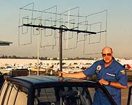 While a Doppler may be useful in some ELT tracking situations (such as a false alarms from aircraft on an airport runway), it is not a universal tool. ELT signals from actual crashes are usually very weak and of mixed wave polarization. Experienced Civil Air Patrol (CAP) volunteers in my area prefer cubical quads and phased arrays (such as the L-Per) instead of a Doppler when in such weak-signal situations. The photo shows a dual frequency (121.5 and 243.0 MHz) stiff-wire quad built by Bob Miller N6ZHZ, Commander of Brackett Composite Squadron 64 in La Verne, California. He says, "With the quad, I am able to pick up a 243 MHz ELT two to five miles miles before the L-Per's antenna will hear it. When there are two or three ELTs chirping simultaneously in hangers at an airport, I use a high-gain quad to track one at a time, listening to the differences in tone sweep rate of each one."
An RF attenuator should be used with an RDF quad to allow S-meter bearing readout and to help determine how close you are to the ELT. Plans for suitable quads are in THRDFS. For more on CAP and tales of searches for ELTs, see Homing In for April 1994.
Q: Can I use the Roanoke (or other) Doppler on the 10-meter ham band and/or the 11-meter Citizens Band?
A: It could be done if:
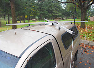 Of course this is not practical on a car, but could be considered for a fixed installation. Remember, Dopplers need carrier-type signals, so you can track amplitude-modulated signals (in FM mode) but not SSB signals. I have experimented with the Roanoke Doppler on 6 meter (50 MHz) FM signals, using resonant whips spaced in a four-foot square. They fit on the roof of the van, but there wasn't enough ground plane area around the whips, and the whips were so tall that they waved around too much while driving. Compared to baseline two-meter performance, this didn't work very well, especially in motion. On the other hand, the 6-meter doppler installation of Robert Haggard AD6XJ (photo at right) works much better. He uses four vertical dipoles made with helical whips mounted around the sides of the vehicle.
Q: I'm thinking of mounting a Doppler RDF antenna on top of my home ham station tower. Any suggestions?
A: One problem with remote operation of the array will be rf losses in the coax. You will probably not have problems with long control lines, although some added protection from lightning-induced transients is in order. For tower mounting, I recommend using four vertical dipoles (which would look like the marine DF antenna photo in THRDFS) instead of whips on a ground plane. This will give better performance by minimizing mutual coupling between the whips.
Q: OK, how about putting the Doppler at our mountaintop repeater site to find jammers on the input?
A: There are many pitfalls in the way of remote mountaintop RDF systems. I get letters regularly from hams who tell me about the wonderful linked RDF systems at repeater sites that they'll be putting on line "real soon now." I encourage them to send me all the details of their results, with photos, so I can tell the world via Homing In. Then I never hear from them again.
You'll probably discover, as they do, that you won't be able to successfully operate a Doppler DF at your repeater site. Here's why:
Fast-switched dual-antenna RDF sets such as TDOA's will probably have similar problems. You might consider a slowly rotating beam with some sort of direction indication through the repeater---this was done by the Happy Flyers organization many years ago.
I know of only one successful remote repeater-connected RDF system now in operation, and it is not a Doppler. (If you know of others, please enlighten me.) This system uses a phased array which is switched very slowly (every second or so) to avoid the problems mentioned above. That slow switching is OK in the user's application, because it is intended to track continuously-transmitting ELTs, not ham-band kerchunkers.
So if you want to use Dopplers for remote RDF, put them at sites that are not associated with repeaters or other VHF/UHF radio systems.
Q: I have read several articles on 2-meter Dopplers and they all specify different antenna element spacings. What is the best?
A: No matter how many whips or vertical dipole elements in a Doppler array, the adjacent elements must not be more than 1/2 free-space wavelength apart, to avoid ambiguous bearings due to phase steps of greater than 180 degrees. Furthermore, adjacent element spacings of greater than 1/4 wavelength will produce phase steps of more than 90 degrees, lowering the level of the recovered audio tone and worsening the signal-to-noise ratio. With that in mind, an optimum adjacent-whip spacing for a 4-whip mobile array for VHF or UHF is slightly less than 1/4 wavelength at the highest frequency to be used. Plans for the 4-whip Roanoke Doppler in THRDFS call for 18-inch whip-to-whip spacing, which is 0.22 wavelength.
The array doesn't have to be this big, but don't make it too small, either. Deviation of the recovered Doppler tone is a function of antenna size and speed of rotation, as given by the formula on page 121 of THRDFS. This works out to about 0.5 KHz deviation for the Roanoke Doppler 2-meter antenna, which is a good value. A super-small array such as the 0.07 wavelength-on-a-side mentioned in the Dick Smith literature won't work well, because the recovered Doppler tone out of the receiver would be only 0.1 KHz. It could be readily overpowered by modulation audio and noise.
If you use a mag-mount implementation, remember to place the whips in a perfect square pattern. Measure spacing carefully or make a template. A slightly rectangular or trapezoidal pattern will introduce significant bearing errors at some angles.
Q: What about the spacing if I use more than four whips?
A: Going to 6, 8, 12 or more whips, as provided for in some Doppler sets, provides little improvement if the array size (radius of rotation) is the same as for 4 whips. If the array size is the same, the Doppler tone deviation is unchanged, so there is no signal-to-noise improvement. There are fewer high-order harmonics in the recovered audio, but that's unimportant if a very narrow passband filter is used, as in the Roanoke Doppler. Furthermore, the closer element spacing of a same-size-but-more-whips array increases inter-whip RF coupling, which degrades performance in multipath.
To fully realize the advantages of more whips, the array size must be increased. Consider an 8-whip array for the two-meter band in an octagon pattern of 18 inches per side (i.e. the same adjacent whip spacing as the Roanoke Doppler). Radius of rotation is more than double that of the 4-whip Roanoke, giving over 1 KHz Doppler tone deviation at the same rotation rate. The array aperture is more than doubled, which improves performance in multipath.
However, such an array, which has a diameter of almost 4-1/2 feet, won't fit on most vehicles, especially when you remember that you would need 7-1/2 feet total diameter to provide an optimum ground plane under the whips. A similar size (in wavelengths) array for the 70 cm band (450 MHz) would be only 2-1/2 feet diameter, which is practical.
Q: Why doesn't the Roanoke Doppler use RF preamps and/or "soft switching" in the antenna system to give more sensitivity and less noise?
A: Questions like this are based on three assumptions:
I disagree with all three assumptions. Here's why:
In summary, I believe that a properly designed PIN-diode switcher (with correct ON and OFF biasing), when used with a sensitive narrow-range receiver, gives as good or better overall Doppler performance (in both sensitivity and multipath accuracy) than any preamp-based design does, whether hard or soft-switched.
Q: Our club wants to set up some RDF sites to automatically find jammers and display their locations on the Internet. How do we do it?
A: First, understand that you won't be able to use such a system to positively identify RF coming from a specific house or apartment at a distance. Let's say you set up a RDF system with three sites to cover a typical urban area of 20 X 20 miles. For good coverage of the area, the sites will have to be on the perimeter. Assume that you can find enough quiet sites and link them. Now assume that the jammer is right in the middle of the triangle of sites (best case). The intersection of your bearings and their uncertainties will create a polygon with an area of about 4 square miles! That certainly won't be good enough evidence for the FCC. There are about 10 hams per square mile in my city, probably the same as where you live. So you'll still have to do plenty of close-in DFing to verify the actual perpetrator's site and get eyewitness evidence.
Why the large polygon? Because the inherent uncertainty of a bearing from a typical VHF 4-whip Doppler in an urban environment is about +/- 5 degrees, even if you have 10-bit readout precision. Sometimes, the bearing error is even greater, especially at fixed sites. (See Chapter 18 of THRDFS.)
This is not intended to discourage you, just to add a healthy dose of reality. If you want to link up RDF stations, consider Automatic Packet Reporting System (APRS), which allows packet radio interconnection of a limitless number, both fixed and mobile, close-in or far away, each one displaying their own and everyone else's bearings. Bearings and station locations can be input to APRS either manually or automatically, so even base stations with beams can help out. For more info, see my Homing In columns in 73 Magazine for October 1994, January 1995, and February 1995.
Contemporary microprocessor-based Dopplers such as the WB6EYV Pico-Dopp have serial (RS-232) output in "Agrelo format." Some older discontinued sets such as the Agrelo DFjr, the Global TSCM DDF2020T, the MFJ Enterprises MFJ-50005 and the AHHA! Solutions Microfinder also put out this format. For bearing display and triangulation with these sets, consider the GoogleHunt program for Windows by Bob Simmons WB6EYV and SigTrax for Apple and Android devices by Jim McCullers WA4CWI. Both are described in detail in the Apps for Hidden Transmitter Hunting page of this Homing In site.
Q: How can I interface my Doppler to APRS?
A: Most non-microprocessor homebrew or kit-built Doppler RDF sets with 8, 16, or 32 LED indicators can be connected to APRS using a circuit developed by Robert Swain KJ4SR. This includes the Roanoke Doppler, the Dick Smith RDF and the DoppleScAnt from QST in the 70's. Robert's circuit takes the binary information from the LED drivers and outputs a serial RS232 data stream of ASCII characters representing directions. For details, see Doppler-to-APRS interface at this Web site and Homing In for August 1995.
Some vintage models made by Doppler Systems feature RS232 serial output consisting of 3-digit numerical readout of bearing in degrees. Doppler Systems sets in the 3000, 4000, and 5000 series can also be used with the Swain interface.
Q: Why are there only 16 LEDs on the Roanoke Doppler?
A: The Roanoke Doppler was designed for the best combination of simplicity and performance. A 16 LED display is usually quite adequate for tracking signals when mobile in urban areas. It gives a rapid indication of which way to drive when time is of essence. I still use my 16-LED unit on the local hunts with good results. When I need higher accuracy for triangulation, I switch to a beam.
Finer resolution is possible with some circuit changes. Tom Curlee WB6UZZ has designed a version with digital readout to the nearest degree. But the basic bearing accuracy of VHF Dopplers on vehicles is typically +/- 5 degrees, so such a display gives a false sense of accuracy. And all these improvements require more complexity. That means more parts to find and greater cost. We have found that most hams want maximum simplicity in projects they have to build themselves. (On the other hand, when they buy a ready-to-use piece of gear, they want maximum bells and whistles.)
Q: Can you help me get my (choose one) Agrelo, Ramsey, Dick Smith, or "bow-tie" RDF equipment (not in THRDFS) to work?
A: Mail about these units is so frequent that I have posted separate pages about each of them at this site.
Q: I can't get my Shrunken Quad to work. What's wrong?
A: Most likely you are using the wrong piston trimmers, but it could
also be an improperly built balun. Go to More on the Shrunken Quad to find out.
Q: Are there any updates/corrections to ______ (fill in your favorite project in TRANSMITTER HUNTING---Radio Direction Finding Simplified)?
A: Click here to get the latest updates to THRDFS.
Q: Where can I find boards/kits/parts for your projects?
A: I try to locate inexpensive sources for uncommon parts and include them in all my
project articles. For updates and additional parts/boards info, jump to the Hardware Resources page at this site.
Q: My club wants to start transmitter hunting but first we need a hidden transmitter. What is available?
A: The answer depends on several factors, so it is now covered in detail within the Foxboxes for Mobile and On-foot Transmitter Hunts page. Also, there is a complete chapter of clever transmitter hiding ideas and another chapter on foxboxes in THRDFS.
Q: I need a miniature transmitter to put on my prized possession (sports
car, TV set, motorcycle, coonhound) to find it after it wanders away or
is stolen/abducted. What is available?
A: Yes, I have actually had inquiries about tracking devices for each of
the above examples, and many more! Unfortunately, it is still true that you get what you pay for, and no matter what you pay, there's no assurance of success.
In the under-$40 category are "experimenter" micro-transmitters sold by companies such as Amazing Devices and ElectroKits. These "bugs" typically use the 88-108 MHz FM broadcast band, where low-power unlicensed transmitters are permitted by FCC Part 15. Manufacturers sometimes claim range of three miles or more for these FM micro-transmitters. But that range assumes high-gain antennas on both transmitter and receiver. A practical antenna on a stealth radio tag will seldom be large and efficient enough for that. Furthermore, if one were to actually achieve three-mile range with such a transmitter, that fact alone would demonstrate that the field strength is in excess of that allowed by FCC Part 15 rules for unlicensed devices in the USA. In other words, it would be illegal operation of a radio transmitter in the eyes of the law.
Some of these experimenter FM-band transmitters use simple L-C tuning, so the transmitter tends shift frequency due to temperature changes, battery voltage droop or proximity to other objects. Futhermore, the FM broadcast band is not suitable for covert operations, as the tag can be tuned in on every home and car radio within range. Usable tracking range is severely limited by interference from powerful broadcast stations. The high level of audio FM deviation (+/-75 KHz) used by transmitters and receivers in the FM broadcast band is not compatible with narrowband Doppler RDF techniques. Have I convinced you that this is not a good option for most applications?
You might be tempted to employ one of the VHF/UHF Amateur Radio mini-transmitters that are described in the foxboxes page. But amateur frequencies may be used only by licensed ham radio operators, with proper transmitter identification, in accordance with FCC regulations. Plenty of ham radio T-hunters are ready and eager to track down intruders on these frequencies, and they won't be amused if they discover that a non-ham is using their spectrum space to keep track of his cat. There are restrictions and/or license requirements for the use of most other VHF and UHF frequencies at these power levels as well.
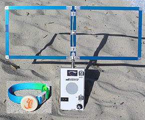
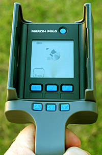
New on the market for keeping track of pet dogs and drones is Marco Polo by Eureka Technology Partners (photo at left). This sophisticated system uses short spread-spectrum signal bursts near 900 MHz to monitor up to three items simultaneously. It sounds an alarm when any of them leave an electronic perimeter and it gives Doppler directional indications toward the wayward critter's collar tag for recovery. A product review is in my Homing In column for Winter 2013.
If money is no object, consider the "kidnap hostage tracking" systems sold by "spy market" distributors such as DPL Surveillance and Spy Mall. Note that even with their high prices, there are practical limits on range and battery life. All advertising claims must be taken with more than a grain of salt. None of these providers offer any guarantees that you will locate whatever you're tracking or even that you will hear a trackable signal.
For vehicles, don't overlook LoJack and other commercial tracking systems. LoJack transmitters are installed in an undisclosed place in your vehicle or other important asset and activated automatically when it's reported stolen to the police. Then the signal is received and RDF-tracked by police and sheriff cruisers and aircraft (over 400 in the Los Angeles area alone). Ask the LoJack salesman if the guarantee of your car's return is still offered.
There are also non-RDF vehicle and pet tracking systems such as the GPS-based systems sold by Tractive, Brickhouse Security and Lightning GPS. Some of these require service subscriptions. (Reports from users wanted, please let me know your experiences by e-mail.)
Q: What about a pager-sized tracking device to put on toddlers? Parents would carry a pocket-sized receiver so that they could locate the child in case he/she became lost.
A: As you can imagine, the tracking of children is a much more serious and difficult matter than the tracking of cats and sports cars. Here are just some of the many factors that must be considered if direction-finding technology is to be used:
Several startup "personal tracking" companies, such as Protect Me Toys, eWorldTrack, Wherify Wireless, and Digital Angel have received considerable press (and resulting investor attention) for their claims of long-range positioning and tracking, especially of children. All now appear to be out of business except for Digital Angel, which has switched to RFID (see next question) and PLB sales. None of these companies' human tracking systems employed traditional direction finding (i.e. beacon transmitter and RDF gear). Instead, they were based on wearable Global Positioning System receivers with radio transmitters that would beacon the GPS data to trackers directly or via cell/PCS phone systems. There were large, had short battery life, and required a clear view of the sky for accurate positioning, making them more appropriate for tracking vehicles or heavy equipment. Smaller versions are now available from Jiobit and AngelSense but one problem still remains: A savvy child abductor can quickly remove such a device from the child or shield it to render it inoperative.
Project Lifesaver is a national program under which law enforcement agencies track victims of Alzheimers Disease or dementia who wander away from home or from care facilities. The subjects wear wrist transmitters that send "dits" continuously on allocated frequencies near 218 MHz. When a "tagged" person is reported missing, the signals is tracked, often with assistance from RDF-proficient volunteers. Read about it in my Homing In column for Winter 2008.
Other RDF-based systems now on the market for tracking children and adults include the medium- and high-end solutions described in my answer to the previous question, with the usual power, range, and battery limitation. If you have personal experience with any of these products, good or bad, or if you discover any other suitable (or unsuitable) systems, please let me know the details by e-mail.
Companies such as Securitas Heathcare systems make "perimeter protection" systems that sound an alarm if a tag-wearing individual wanders or is taken out of a protected area. These systems are marketed to health care facilities as alarms to provide early notification of wandering patients, or of infant abductions. They are based on RFID technologies (see next question), so they often don't have any direction-finding capabilities. The protected perimeter is non-portable, and the tags can't be used to help find the person once he or she is outside the protected area. By contrast, Care Trak, Incorporated sells a system of wrist/ankle transmitters that combines perimeter alarm and short-range (up to one mile) RDF tracking.
Q: Our construction company is losing small tools, either by accident (falling into holes) or theft. Can a transmitter be inserted into items like wrenches, drills or grinders, with a RDF unit capable of detecting them inside a car trunk?
A: Radio Direction Finding (RDF) technology is typically done at considerable distance (from yards to miles and beyond). To do that, transmitters require long-term power sources (such as batteries) and antennas. They're usually too large to be placed on or in a hand tool. In addition, the transmitted signal can be detected by anyone with a receiver tuned to the proper frequency, so these systems are not covert.
RFID technology at the jobsite exit is probably more appropriate for this tool-detection application. RFID systems track property and objects at relatively close range with unique codes. For instance, chips (also called tags or transponders) can be implanted in pets to provide positive proof of ownership if the pet strays into the pound or is stolen. A reader device, passed over the chip, detects it and reads out the chip's unique ID code. Similar RFID systems sound an alarm when non-paid-for merchandise passes through the doors of a store. RFID done at greater distance in automatic toll collection systems on and elsewhere. At one time, the FasTrack transponders for southern California toll roads could even be used to quickly pay for a McDonald's burger at the offramp. (This feature was discontinued because so many transponders were being stolen out of cars and then used for this purpose!)
In an ideal situation, the chips are "passive," meaning that they don't require battery power. They usually cannot be detected with conventional receivers, but only by a reader or polling device designed to be used with them.
Q: I'm ready to go on a mobile T-hunt. How do I find one?
A: If you live in southern California, see the Southern California Transmitter Hunters page for mobile T-hunts in the Los Angeles, Orange County and San Diego County areas. Long-time enthusiast Byon Garrabrant N6BG publishes a list of regularly-scheduled hunts, both mobile and all-on-foot, at foxhuntlist.com. He welcomes submissions from anywhere in the USA. Web sites about some groups that do mobile T-hunts are in the Links page of this site. If there are no hunts in your area now, get together with your local ham club members and start them!
Q: I read your book and your Web introduction to mobile T-hunting, but I want to buy some VHF/UHF RDF equipment for my car instead of building it myself. What's available nowadays?
A: Commercial quad antennas suitable for vehicle mounting are available from Cubex, both 144 MHz and 440 MHz bands. Compact yagi antennas for 144 MHz and 440 MHz bands are available from Arrow Antennas. You will have to design your own rotating mounts for these quads and yagis. Information on simple mounts is in Chapter 7 of THRDFS.
The PicoDopp by Bob Simmons WB6EYV is a fine choice for an inexpensive Doppler add-on for mobile T-hunting. The circuit boards are all assembled and tested for you. However, you will need to provide your own enclosure and antenna platform. A supplier of ready-to-use professional-grade Doppler sets is Doppler Systems LLC.
Q: My friends and I chat on the local two-meter repeater. Somebody on there transmits beeps and mocks us. We can all hear him on the input of the repeater. Please listen with your direction finding equipment. We need to stop him.
(Believe it or not, requests for me to listen on VHF/UHF have come from hams that are hundreds of miles away from me!) You and your friends need to put some RDF gear on your vehicles and track down the offender yourselves. That's why I have this site and my book --- to help hams like you become proficient at RDF. Once you find him or her, a little friendly persuasion may be all that it takes to eliminate the problem. If not, the chapter on solving malicious interference problems in THRDFS may be helpful in developing a strategy. The Volunteer Monitor Program of the American Radio Relay League may be able to assist you.
A few hams have developed similar fingerprinting systems. The first was "XMIT_ID" by Richard Rager KB8RLN. It used PC software and an 8-bit Soundblaster card. Richard's callsign is expired and he is listed as a silent key, but project files can still be downloaded from N9ZIA's site.
"Sherlock" by Malcolm Mallette WA9BVS also runs on a PC and uses its sound card with commercial oscilloscope software. The newest version of Sherlock, which works with Windows XP and Vista, was detailed in a feature article by WA9BVS in the Winter 2006 issue of CQ VHF magazine. Click to download this article in PDF format (7 MB), courtesy of WA9BVS.
Q: What is a Crenshaw Factor and why do I need one?
A: The Crenshaw Factor has been used for many years in southern California T-hunts to
normalize mileages and account for odometer differences between various vehicles. Your
vehicle's Crenshaw Factor is the odometer mileage you get when you drive a standardized course
that runs along Crenshaw Boulevard for about 9 miles. The course was chosen because it is
relatively straight and goes up to the start point of the All-day hunts. This makes it easy for hunters
to check their factors regularly on the way to a hunt.
A big problem right now is that the landmarks at the start of the Crenshaw have changed. The
official start point is in front of a now-gone telephone booth in front of a now-gone Winchell's
Doughnut shop on the southwest corner of Artesia Boulevard and Crenshaw. If you can find this
point, then all you do is record your odo reading and drive in the left-hand lane along Crenshaw to
the stop sign at Crest Road in Rancho Palos Verdes. Your elapsed mileage to that point is your
Crenshaw Factor.
Nobody knows exactly what this distance is, but it doesn't matter. To normalize mileages on a
T-hunt, each vehicle's elapsed odometer mileage is divided by its Crenshaw factor. The result is
in "Crenshaw Units." The team with minimum Crenshaw Units wins.
Example: Say your odometer mileage on the hunt is 35.7 and your Crenshaw
factor is 8.8. Your Crenshaw Units are 4.057. You think you won, but another
hunter has odo mileage of 36.8 and Crenshaw factor of 9.3. That means his odo
reads higher than yours for the same distance traveled. His Crenshaw Units are
3.957, so he beat you.
It is commonplace for two or more hunters to have low mileages within a few
tenths of one another. Crenshaw Factors are needed to determine winners on
many of our milege hunts, so it is important for every hunter to have one.
Q: I have a ham store and would like to carry your book. Do I have to get
it from ARRL?
A: Retailers and dealers should get books directly from the publisher. Call McGraw-Hill Trade Order Desk at
(800) 722-4726 to place quantity (5 or more) orders.
Q: Is there any difference between ISBN number 007-1560068 and ISBN number 0-8306-2701-4 for your book?
A: The book has two ISBN numbers because one was assigned to it by TAB Books originally and the second was assigned by McGraw-Hill when McGraw-Hill acquired TAB Books. Booksellers might show stock in either ISBN number, depending on when they ordered the book and put it into their computer system. Sorry for the confusion, but I have had no control over this process.
Q: Can I make and sell kits and boards for projects in your books and articles?
A: Since Tom Curlee and I don't have the time to get into the board/kit
business, we welcome other enterprising hams supplying these products. However, our publishers insist that we protect the copyrighted material appearing in the
book and my magazine columns. Kit/board suppliers must not duplicate, sell, or
give away any of the TAB/McGraw-Hill or 73 documentation of the
projects. Kit/board buyers should be urged to purchase THRDFS for the
tune-up, calibration, installation, and operating details. This works out
well, because some of our kit suppliers have made extra money by retailing the
book! To purchase books wholesale (5 or more copies), call the "trade
order" desk at TAB/Mc-Graw-Hill. Please note that Tom and I support the
circuits in our book, but we accept no responsibility for performance of
third-party boards and products.
This page updated 10 July 2025
 A much better choice would be the tiny transmitters and tracking receivers made specifically for tracking mammals, reptiles, birds, fish and even insects. See my RDF links page for commercial suppliers of transmitters and receivers that are popular with two market groups: wildlife researchers and the owners of prize hounds. For official law enforcement use, similar but more powerful transmitters certified to FCC Part 95 are available to provide greater range.
 To save battery life, these critter-tracking transmitters send "dits" that are a few tens of milliseconds long, once every second or so. Their low-power signals are so weak at long range that dual-antenna sets and Dopplers are at a disadvantage. Sensitive narrowband receivers and beam or phased-array antennas work best. Professional grade tracking receivers such as the Com-Spec Model R-30M are expensive. Another option is a consumer-type scanner. It must be multi-mode model such as the Icom IC-R10, IC-R20, Trident TR2400 or Sony ICF-PRO80, which include CW/SSB (BFO) modes. For a tracking antenna, you could build a small cubical quad from plans in THRDFS.
 A: The concept of transmitter fingerprinting was invented and patented in the 1980's by Phil Farrell K7PF of Seattle. He licensed his patent/technique to The Boeing Company and to Motron Electronics, which sold equipment for it for many years. The Motron implementation (called TxID) consisted of a card that plugs into the expansion slot of a PC, plus software running under DOS. I tested and reviewed the system in Homing In for November 1994. The review explains the principles of fingerprinting and shows good and bad points, including comparison of some same-model transmitters. Later, Motron added features such as receiver frequency control and readout for remote operation. TxID will control a tape recorder for evidentiary purposes. You may be able to find it on the used market.
 Back to the Homing In home page