All updates apply to first printing, June 1987. The publisher may have incorporated some updates into later printings.
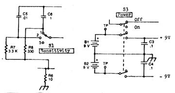
1. Page 170: On Sniff-Amp schematic Figure 12-7, exchange the designations of S1 and S3. S1 is the three-position sensitivity switch that can be implemented with either a rotary type or a SPDT center-off toggle switch. The toggle switch method was used on the model shown in photograph Figure 12-8, page 172, below and to the left of the meter. Position 3 of S1 is the center-off toggle position (least sensitivity). S3 is the 3PDT power ON/OFF switch, slide or toggle, with no center position. In the ON position, +/- 9V (not -94) is applied to AR1. In the OFF position, +/- 9V is off and R15 is connected from the tuned circuit to the meter to give absolute minimum sensitivity for very close-in sniffing. In the model of Figure 12-8, S3 is on top of the box next to the coax connector and is not visible in the photo. Corrected portions of schematic are below.
2. Page 123: Dick Smith Electronics no longer has offices and stores in the USA. The DF unit has been discontinued and is no longer available. If you own a Dick Smith DF, read Design improvements for the Dick Smith K-6345 Doppler at this Web site to improve its performance.
3. Page 224: On Bunny Box synthesizer schematic, R13 should be 470K, not 470 ohms.
4. Page 53: On S-meter bridge circuit, Figure 5-9, the negative power supply lead connects to point "D"
5. Roanoke Doppler:
6. Page 9: Typesetting error. First line on page should read "[] Accuracy and Resolution. Forgetting the effects of the..."
7. Page 244: In Figure 17-4, the left lead of C1 should be connected to shield/ground in addition to the loop, as shown correctly in Figure 17-3.
8. Page 148: Fourth paragraph should read "...At 4.5 wavelength spacing (about 30 feet at two meters), for instance..."
9. Page 107: The 5558 is a Signetics part number for a dual op-amp. Each half is the equivalent of a 741. It can be replaced by the MC1458, manufactured by Motorola and Texas Instruments.
10. Page 173: For additional detail on the Shrunken Quad project, see the More on the Shrunken Quad page of this Homing In site.
11. Appendix A, Manufacturers and Organizations:
Some THRDFS readers have reported difficulty finding the DS75492 inverter-driver ICs used in the 16-LED display option of the Roanoke Doppler project. The following modification by co-author Tom Curlee WB6UZZ replaces four chips (U201, U202, U203, and U204) with one 74HC4514, which can be found at Digi-Key and Jameco for less than two dollars (0.3-inch lead spacing package). Using this high-current CMOS device allows you to readily control the brightness of your display, too.
Click on the mini-schematic (or use your browser's image download feature) to get the full-sized schematic, which shows three methods for brightness setting:
If you have a circuit board based on the schematic in THRDFS, you can probably incorporate this modification by simply doing the following:
U202-14 to U202-1
To insure full output drive from the 74HC4514, make sure that its supply voltage (Vdd) is at least +5.0 volts, but do not exceed +5.5 volts. LED current for daylight use should be 15 milliamperes (mA) nominal, 20 mA maximum. Select the dropping resistor to achieve this current with the specific LEDs and Vdd value in your unit. Try 47 ohms for starters.
Although they cost more than ordinary T1-3/4 size LEDs, high-efficiency LEDs such as the SLA580LT3F (Radio Shack 276-066B) provide the best daylight performance in doppler displays. At 15-20 mA, high efficiency LEDs may be too bright for night use. If so, use the optional dual or variable brightness circuits to dim your display for nighttime. Choose values for R1 and R2 in the dual-brightness circuit by experiment.
Output drive of HC devices decreases with temperature, so the LEDs may dim if your display is on the dashboard in direct sunlight on a hot day.
No liability is assumed with respect to the use of the information in this
update sheet or the text to which it refers.
For printed circuit board sources for projects in this book, see the Hardware Sources page at this Homing In site.
If you have an update, please e-mail it to k0ov@homingin.com. Thanks!
This page updated 22 February 2019
Roanoke Doppler Display Update
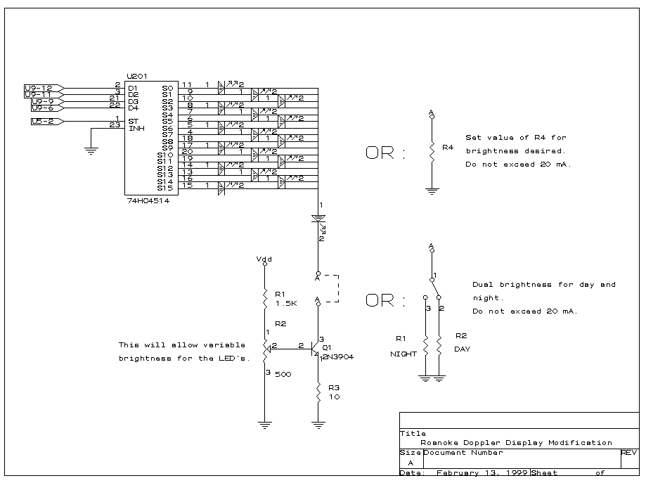
U202-3 to U202-2
U202-5 to U202-6
U202-12 to U202-13
U202-10 to U202-9
U202-8 to U202-7
U203-14 to U203-1
U203-3 to U203-2
U203-5 to U203-6
U203-12 to U203-13
U203-10 to U203-9
U203-8 to U203-7
U204-14 to U204-1
U204-3 to U204-2
U204-5 to U204-6
U204-12 to U204-13
 Back to the Homing In home page