Using and Improving the Agrelo DFjr Doppler Set

The DFjr is out of production.  Agrelo Engineering, its designer and original manufacturer, went out of business in 1998. SWS Security, the company that bought the DFjr design from Agrelo Engineering, discontinued it in July 1999 and replaced it with The Tracker, a similar doppler set designed and priced for the commercial/military market.  Then SWS Security went out of business after the death of its owner.  This page is on the Homing In site to assist hams who own a DFjr or are considering the purchase of a used one.


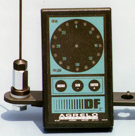
The DFjr display unit next to one of the original (Version 1) antenna whips

DFjr Documentation

In answer to many requests, I regret that I cannot provide schematic diagrams of the DFjr hardware (display/antenna units) or source code of the software.  The manual available for download below is for Version 1.21, which was probably the last version produced by the company.

Download the DFjr instruction manual in PDF format (500 KB)

DFjr Advertising Flyer

Bernie Hunt K2YO has provided a copy of the original DFjr advertisement, showing the introductory price of $299.  Thanks Bernie!  The antenna set pictured in the flyer is Version 1, with one large magnet in the center under the switch box.

Download the DFjr brochure in PDF format (982 KB)

DFjr Product Review

The DFjr set that I reviewed was one of the first ten off the production line.  I got it in early May 1996. As with many early-run products, there were problems, particularly in the antenna system. I reported the problems I observed to the company and closely followed the reports of others on Internet mailing lists and the corrective actions that were taken.  Three major revisions and many T-hunts later, my review was complete and submitted for a two-part Homing In series to run in the May and June 1997 issues of 73 Amateur Radio Today magazine.  Then the 73 editorial staff had a mind change and asked for a standalone review article instead.  Many discussions followed and the end result was that the review was shortened and published in the August 1997 issue.  The review article will help you determine which version of the antenna system you have and what changes, if any, need to be made to it.

Download the KØOV review of the DFjr in PDF format (180 KB)

More DFjr Antenna System Improvements

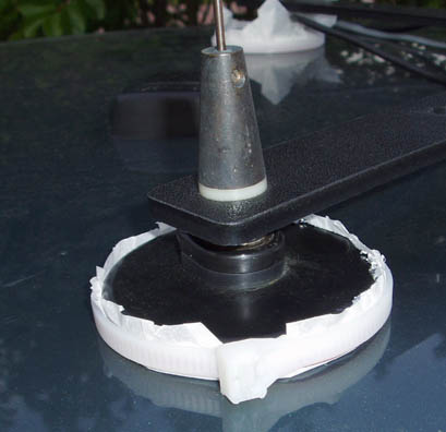
In a multi-part Homing In series on Dopper RDF techniques and technology, I wrote the following paragraphs for the Spring 2004 issue of CQ VHF Magazine about simple ways to improve performance of the DFjr antenna system.

It's the antenna system that makes or breaks a Doppler from a performance standpoint.  And as I explained in a previous article of this series, there is one principle that is paramount, but not intuitive:  An ideal Doppler RDF array is perfectly non-directional in amplitude.  Due to AM-to-PM conversion in the receiver's limiter stages, any factor that causes the strength of the signal at the receiver input to vary as the Doppler array is electronically "rotated" will result in the bearing display being jumpy, hard to interpret and perhaps even downright unreliable when used in a moving vehicle.

Unwanted amplitude directivity can be caused by improper positioning of the array on the vehicle, by mutual coupling among the elements, and by improper feedline routing.  Another cause that is frequently overlooked by both amateur and professional designers is termination impedance (loading) of switched-off elements in the array.

How bad are these directivity-induced fluctuations?  They would be hardly noticeable if there were no terrain features or objects to reflect the signal.  But such an environment rarely occurs.  Almost anywhere that you are likely to drive, there will be a plethora of these reflected signal sources, commonly called "multipath."

For a given amount of multipath, the effect on a particular Doppler installation depends on a number of factors including the receiver's IF filtering and discriminator performance.  The sharpness of the audio bandpass filter in the Doppler display unit also plays an important part.  Observing the fluctuations by eye under varying terrain conditions isn't a very scientific way to compare Doppler arrays.  It's much better to test in a consistent environment and to record the actual fluctuations.  This isn't difficult if the Doppler set has serial directional data output.

There are several formats for serial bearing data streams. Perhaps the most popular at present is the "Agrelo" format, named after the manufacturer of the DFjr Doppler set introduced in 1996.  In this format, the 360-degree azimuth range is described by 256 bits, each bit representing about 1.4 degrees.  Format is "%xxx/y" where xxx is the relative bearing rounded to the nearest degree and y is the quality of the bearing.  Quality is a computed function of the spread of the data points in the sample period and ranges from 1 (worst) to 8 (best).

Years ago, tests like this would be done with data plotted on an analog strip-chart recorder, complete with a motor, pens, ink, and special paper.  Nowadays it's simple (and much less messy) to let a PC or PDA do the work.  Figure 1 is a PC-generated "strip chart" of a stock DFjr's bearing fluctuations along a test track as taken by Mike Musick NØQBF, who lives near St. Louis, Missouri.  Mike and I have experimented with and corresponded about various Doppler arrays for over a dozen years.


Figure 1.  NØQBF's chart of bearing fluctuations along a 5-mile test track with an unmodified mag-mount Doppler array as supplied with the DFjr RDF set.  His software plots the difference between displayed bearing and actual computed bearing at 200 points along the route.  (Courtesy NØQBF)

I don't know the details of Mike's test track, but it's probably similar to mine.  There are two that I use to test two-meter Dopplers and other VHF and UHF RDF sets.  Both are conveniently located here in Fullerton and make use of local repeaters.  Each is about two miles from a repeater and is about a mile long.  In either case, I drive directly toward the repeater's transmitting antenna, observing bearing indications on the repeater output signal.  One track is in a suburban business area with the repeater antenna visible in the distance.  The other is on a residential street with the repeater tower obscured by a rise in the road.

For calibrating mobile Dopplers and for observing their readout accuracy and steadiness, your vehicle must be in motion. This increases the effective baseline of the antenna system by averaging the fluctuating indications, either by eyeball or by averaging circuits in the Doppler set.  When moving directly toward the test signal, it's easy to calibrate the display for a straight-ahead indication.

There is a lot of bearing fluctuation in Figure 1, suggesting that Mike's array was directional in amplitude -- not good.  He had already selected his vehicle roof mounting and optimized his cable routing for non-directivity, so he became suspicious of the RF path for the counterpoise on the DFjr's supplied antenna set.

NØQBF wrote, "With each new generation of whips, Agrelo Engineering improved the electrical contact between coax shields and magnet cups.  But the magnets themselves are nonconductive and there are vinyl covers on them to protect the vehicle's finish."  Mike realized that this resulted in very little RF coupling from the shields to the ground plane provided by vehicle roof.  Most mag-mount antenna suppliers cover the magnet with grounded foil to provide capacitive coupling to the vehicle body (photo below), but this was not done on DFjr arrays.


The Larsen mag-mount antenna base at left has a metal foil bottom to provide RF capacitive coupling to the car body.  There's no foil on the DFjr Doppler antenna magnet at right. (KØOV photo)

NØQBF disassembled his array and sandpapered the paint from the magnet holders.  Then he covered them top and bottom with copper foil shielding tape (#1181 from 3M Company, which has conductive adhesive).  He ran the test track again and got the results of Figure 2.


Figure 2.  Plot of DFjr array modified with copper foil tape to increase capacitive coupling through the magnets to the metal vehicle roof ground plane.  (Courtesy NØQBF)

What an improvement!  The original array had errors of greater than 50 degrees a significant percentage of the time and a region of 100 to 150 degrees error.  The modified-magnet array was less than 50 degrees off all the time, except for a couple of short flickers.  If you saw the predicted amplitude directivity pattern of a Doppler array with reactive termination in part 5 of this series, this won't come as a surprise.  A capacitance meter check showed Mike that his mod had reduced the series reactance in each whip base from 10 ohms to about 2 ohms.

Analysis of Figures 1 and 2 showed improvement in standard deviation of the bearing error from 63 degrees to 41 degrees, but Mike wasn't satisfied.  He wondered about the aluminum crossarm that holds the DFjr whips in position and provides mounting for the RF switch box.  Could it create unwanted coupling between the whips and thereby produce amplitude directivity?

Mike removed the crossarm, carefully positioned the whips on the vehicle roof without it, and drove his test track again. Results were encouraging, so he fabricated a replacement crossarm from ABS plastic.  With the whips and switch box mounted on it, he drove his test track and got the plot of Figure 3.  Bearing fluctuations beyond 50 degrees were rare, even in the heavy multipath area near the end of his track.

"Standard Deviation is now down to 24 degrees," Mike wrote.  "The cumulative changes are really evident on APRS map plotting.  There is a little wobble from the multipath, but my old 'splattered bearing' problem has completely gone away."


This DFjr antenna array has been modified with a NØQBF one-piece ABS plastic crossarm to replace the stock aluminum arms (but not foil magnet covers).  As in the original arms, there are holes for placement of the whips for the 2m, 125 cm and 70 cm bands.  Separate quarter-wavelength whip sets for each band insure that the antenna elements are near resonance. (KØOV photo)


Figure 3.  Eliminating the aluminum crossarms in addition to increasing the capacitive coupling produced astonishingly better multipath performance in the DFjr. (Courtesy NØQBF)

Is that the best that the DRjr array can do? Probably it is, because the switcher uses monolithic RF preamps with nominal input impedance of 50 ohms.  I showed in a previous article that such resistive/reactive termination results in at least 5 dB amplitude directivity, which is far from ideal.  The dual PIN diode switch circuit in my Homing In Web site would be a good alternative because it provides high-impedance termination of switched-off whips, giving directivity of 1.6 dB or less.

How good is the coupling and symmetry of the ground plane in your mobile Doppler array?  If it has mag-mount whips, verify that there is conductive foil covering the magnets.  If not, add foil tape as NØQBF did.  Make sure that the foil coverage is complete and that the foil or tape is firmly connected to the coax shield.  Any wrinkles in the foil will decrease the capacitive coupling.  Not only must the coupling be excellent on each magnetic base, but the base-to-vehicle capacitances of each one must be equal if unwanted directivity is to be avoided.  After any modifications to your Doppler array, be sure to recalibrate the system, just as you should do when you change receivers, vehicles, or ham bands.


Instead of using foil shielding tape to improve ground coupling, I use ordinary aluminum foil, carefully flattened and bonded both electrically and mechanically to the magnet cups.  To protect the vehicle paint, this foil is covered with parchment baking paper, available at supermarkets.  (KØOV photo)

If your Doppler's self-test features include stepping the RF switcher to each whip individually, as does the DFjr, you can perform a quick-and-dirty check of array directivity.  While monitoring through the array a steady but not very strong signal, such as a distant repeater, observe the S-meter readings as the array is stopped on each whip in turn.  If there are significant differences in signal strength on one or more whips, you have unwanted directivity due to array placement, ground plane or termination issues.  Another possibility is a failed component in the switcher.  Some users have reported preamp failures in DFjr arrays caused by static discharge.  An even more likely cause of preamp or PIN switch failure is accidentally transmitting through it.

So what has happened to the DFjr?  The idea of an inexpensive processor-enhanced Doppler set with serial data output for APRS was quickly and enthusiastically embraced by hams, but technical and production problems kept the flow of finished units down to a trickle.  Finally in late 1998, Agrelo Engineering closed its doors and disappeared, leaving buyers high and dry.  NØQBF and I were soon inundated with inquiries about the company that we couldn't answer because we didn't know the answers ourselves.  Mike compiled a Web page of advice for owners of DFjrs and added it to his PocketAPRS Web site.

About two years after this Homing In column was published, NØQBF decommissioned his PocketAPRS Web site.  However, you can read a cached version of his DFjr Advice Page at archive.org.

Frequently Asked DFjr Questions

Q: I think I may have zapped my antenna set.  How do I fix it?

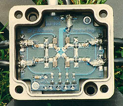
A: According to my correspondence with the engineer who designed the DFjr antenna switcher (shown at right), the monolithic RF amplifiers for the stock DFjr antenna are MAR-4 by MiniCircuits in early units and MAR-7 in later units.  I have heard of some units being "souped up" with preamps from Sirenza.  Any of these amps will fail if transmitted into. Some have reported failures caused by static electricity, but that hasn't happened to me.

If you can't procure MiniCircuits MAR series amplifiers, you may be able to substitute the ERA series.  If you replace one amp, you should replace them all with parts from the same lot, to prevent possible phase differences between channels.

Another option would be to eliminate the preamps entirely and substitute the wide-range antenna switcher circuit in this Homing In site.  I tested this switcher with a DFjr display some years ago and it worked fine.  If you're concerned that my PIN switcher doesn't provide RF gain like the monolithic amplifier circuit does, keep in mind that the monolithic amplifiers have poor noise figure and their input impedance is non-optimum.  (They are InGaP Darlington bipolar, not GaAsFET).  So if you keep your coax to the receiver short, there will be little difference in overall performance.  My passive circuit is much more tolerant of accidental transmissions, but disconnect the mike when you're DFing anyway to be safe.

DFjr circuit board photo

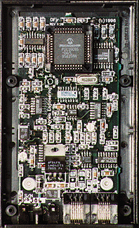
This photo of the DFjr circuit board is actual size if you are using a 72 dpi monitor.

© 2004 and 2008 Joseph D. Moell. All rights reserved.

HOMING IN logoTHRDFS cover Back to the Homing In home page

This page updated 2 January 2017