Wide-Range Antenna Arrays
For the Roanoke Doppler
by Joe Moell KØOV
Originally published in 73 Magazine, June 1995
Doppler units are the "weapon of choice" among mobile T-hunters in many parts
of the country. They indicate the direction of incoming VHF signals on a
circular ring of light-emitting diodes or a digital display. A doppler set
updates bearings almost instantaneously, so even short carrier bursts can be
tracked.
A doppler installation can be done quickly on just about any vehicle. It has a
much lower profile than a RDF yagi or quad setup. The multi-element antenna
assembly replaces your mobile whip. The control unit extracts direction
information from a tone that the antenna set adds to the audio output of your
VHF-FM transceiver or scanner.
Excellent commercial doppler models are available for several hundred dollars,
but you can build your own at a fraction of the cost. Today's most popular
do-it-yourself doppler was originated by Chuck Tavaris N4FQ of Roanoke,
Virginia. Tom Curlee WB6UZZ and I made enhancements and documented the design.
We named it the Roanoke Doppler in honor of N4FQ's T-hunting grounds.
Complete plans for the Roanoke Doppler are in "Transmitter Hunting---Radio
Direction Finding Simplified" by Moell and Curlee. One chapter in this book
thoroughly discusses the theory of RDF using the doppler principle and gives
much more information about techniques, advantages and disadvantages than space
here allows.
The Roanoke Doppler has been built by hundreds of hams in many forms (see Photos 1 and 2 below). Several independent suppliers have made circuit boards and kits available for
its controls and display. They are not affiliated
with the book's authors or publisher, so contact them directly for information
on their products.
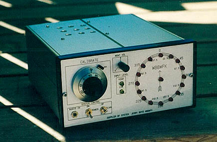
Photo 1 (left). This Roanoke Doppler display box was built by Jerry Boyd WB8WFK of
Albuquerque, NM. Note the 10-turn potentiometer and large dial for the
calibration control. This allows him to log settings for each band. (Photo by WB8WFK)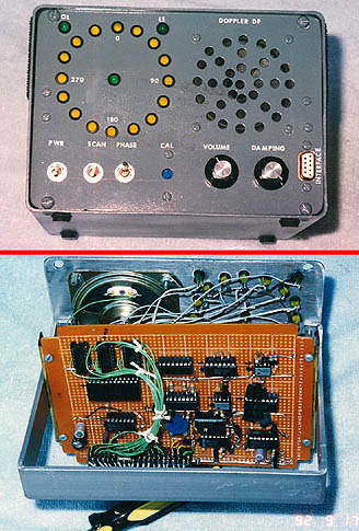
Photo 2 (right). The Roanoke Doppler display circuits are designed for easy "homebrew"
construction. Bill Briles WØOQC of Derby, KS built his on perforated
prototyping board. Etched circuit boards are also available from several
sources. (Photos by WØOQC)
A New Roanoke Switcher
The Roanoke Doppler antenna design in the book (see Photo 3 below) works well on strong two meter
signals. I have used it on well over a hundred T-hunts. But it has room for
improvement. The requirement for exact half-wavelengths of coax limits an
array to a narrow frequency range (typically 5%). Furthermore, readers who
have tried to scale the array for higher frequencies (such as the 70 centimeter
band) have had disappointing results.
Photo 3. The Roanoke Doppler antenna array described in TRANSMITTER HUNTING has four quarter-wavelength whips
on a 20 X 20 inch metal plate with 8 radials to provide a ground plane under
each whip.
In 1994, I designed an improved switching system for the Roanoke Doppler and
invited several T-hunters to build and test it. The new design (schematic in Figure 1 below)
features series PIN diodes at each end of the coax lines to the four whips.
This means that the coaxes can be any reasonable length, so long as the four
lengths are equal. Coax lengths no longer limit the bandwidth of the array, so
it is possible to use one array to cover tens of megahertz, limited only by
array spacing and values of inductors and capacitors in the switcher.
(Why is it important to have diodes at each end of each coax? See Homing In
for April 1995, which explains in detail the importance of controlling both the feedpoint
impedance of switched-off whips and the impedance match at the common point.)
Figure 1. Schematic diagram of the new wideband switcher for the Roanoke
Doppler. The P-in-a-triangle symbol denotes a connection to the ground plane sheet of the one-piece version. For the mag-mount version, the P-in-a-triangle points at the whip ends of the coaxes are connected to the magnets but remain insulated from the car body. Components values are for an array centered on two meters. All capacitors except C26 are 680 picofarads. R101-R104 are 220 ohms. See text for data on D101-D108 and L101-L105.
In the new Roanoke Doppler antenna switcher, PIN diodes receive more current
drive in the ON state (7.5 mA), reducing loss. Diodes are reverse-biased when
OFF to provide better isolation. The new switcher makes the Roanoke Doppler
noticeably more sensitive. It gives bearings on weak signals that would have
been masked by switching noise with the original antenna.
It's not hard to upgrade your present two-meter Roanoke Doppler switcher to use
the new circuit. Most of the existing chokes and capacitors are unaffected.
Just delete half of each two-section RG-174 coax line, put series PIN diodes at
the end of each remaining line, add resistors at the antenna bases, then
install L105 and C109. Note that the RG-174 lines to each whip are soldered to
the plane at both ends, but the shield of the coax to the receiver connects to
the plane through C109.
Changing from shunt to series RF diodes requires minor modifications in the
control unit. The fifth wire in the control cable becomes a positive voltage
source instead of a return connection. D13, D14, C26, and R38 set the
potential on the counterpoise plane and radials at two diode drops below +5V
(approximately +3.5V) instead of vehicle DC ground potential. If you
fabricated the antenna unit as described in the book, using a copper-clad sheet
on a wood base mounted with suction cups to insulate it from the car, DC on the
sheet is not a problem.
Delete the 680 ohm drive resistors (R24-R27) in the control unit, replacing
them with jumper wires. They are no longer needed because this function is
performed by R101-R104 in the antenna unit. If your control unit has an
A-suffix part at U5 (such as CD4049A or MC14049A), replace it with a B-suffix
part to get adequate current drive.
I used Motorola MPN3401 PIN diodes at D101-D108. They are available by mail
(see Hardware Sources page). Other suitable substitute PIN diodes are also listed on that page. Ordinary switching diodes are not recommended. (See the Frequently Asked Questions page for reasons.)
Miniature (quarter-watt resistor sized) rf chokes typically have iron cores.
The distributed capacitance of these chokes gives them self-resonant
frequencies in the 75 MHz range. This is below two meters, so these chokes can
act like capacitors instead of inductors there. Non-ferrous core chokes have
self-resonant frequencies near 200 MHz, so be sure to use them in the switcher
instead of iron-core chokes. For L101-L105, I recommend J. W. Miller #4602
(1.0 uH) or #4604 (1.5 uH), available at many local distributors or by mail from Circuit Specialists and Ocean State Electronics . These chokes
are about the size of a 1-watt resistor.
You can make your own 1 uH chokes on one-inch lengths of 3/16-inch diameter
polystyrene rods. Wind 24 turns of AWG 26 enameled wire on the rod in a single
layer, close-spaced. With the wire held in place with a bit of tape, cover the
winding lightly with Q-Dope, a liquid polystyrene coating made by GC
Electronics. It's best to use this substance outdoors to keep the shack
fume-free. After the coating hardens, strip enamel from ends of the leads and
install the choke.
If you are careful, you can make "air core" chokes without the rod. Wind the
turns on the shaft of a 3/16-inch drill bit, hold down the ends of the winding,
and brush on some Q-dope. When the coating dries, carefully slide the choke
off the bit in one piece and install it. Covering the installed choke with
more Q-dope will prevent it from peeling apart due to road shock and vibration.
(Hint: Finished coils are fragile before the second coating. It's easier to
strip enamel from the wire ends before winding instead of afterwards. It takes
19.5 inches of wire to make a 24-turn coil.)
More Than Two Meters
Theoretically, the radius of rotation of a multi-whip doppler array (the
distance along the ground plane from array center to any whip base) must be
less than one quarter free-space wavelength at the frequency being received.
This means that the four antenna square array pattern must not be more than
0.35 wavelength on a side. My experiments and those of others have shown that
about 0.22 wavelength on a side is optimum.
Closer spacing increases mutual coupling between whips, which in turn increases
undesirable amplitude directivity effects. Furthermore, it produces lower
deviation of the doppler tone in the receiver, degrading the signal-to-noise
performance. Wider spacing increases doppler tone deviation, which can be
detrimental on some receivers, depending on their IF filter characteristics.
A 0.22 wavelength array works well over a +/-20 per cent frequency range. An
18-inch array like the one in the book covers 121 through 174 MHz. Bearing
accuracy is unacceptable outside this range. Sensitivity is maximum near the
resonant frequency of the quarter wavelength vertical whips.
Civil Air Patrol volunteers, Coast Guard Auxiliary members, and others
interested in search and rescue can use this array on the 120 MHz aircraft band
and the 160 MHz marine band. Keep in mind that Doppler processing works only
with FM receivers. A scanner or marine set receives narrowband FM from 138 to
174 MHz, but most scanners and all transceivers have only AM detectors in the
120 Mhz aircraft band. They won't work with a doppler RDF set. Instead, you
must use a receiver that features selectable narrowband FM mode for the
aircraft band
Inductor and capacitor values in the switcher are not nearly as critical as
whip length and spacing, so long as these components have self-resonant
frequencies near the high end of the array operating range. Table 1 below gives
array sizes and component values for doppler antennas centered on three UHF/VHF
bands. For one-piece arrays on a metal plate, length of the corner radials
extending from the whip base should equal the whip length. Turns data for
inductors are for single-layer close-spaced chokes on 3/16-inch non-metallic
forms, wound with AWG 26 enameled wire.
Table 1. Array and component data for the new Roanoke Doppler
switcher for three popular bands.
Mag Mount Version
Some commercial doppler sets have individual magnetic-mount whip bases instead
of a one-piece array. Coaxes from each whip go inside the vehicle to the
switcher, located either in the center of the array or in the control/display
box. One set of whip bases can be used over a very wide frequency range by
placing them on the vehicle roof at appropriate spacing for the frequency of
the hunt.
The requirement for exact dual quarter-wavelength coaxes between switcher and
whips made it impossible to do this with the old Roanoke Doppler switcher.
Coax lengths are not critical with the new switcher (so long as they are equal
lengths). So a mag-mount antenna set is practical.
I built the prototype from inexpensive Citizens Band whips on sale at a local
truck stop (see Photo 4 below). They are manufactured by Barjan Products (Model 300-102). The
large bases make them easy to modify. The whip holder has a setscrew mount, so
exchanging whips for band changes is simple. Other hams have used mag-mounts
by MFJ, Lakeview and other suppliers.
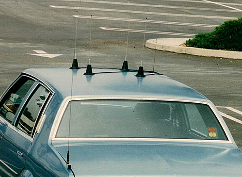
Photo 4. Magnetic-mount doppler whips can be placed quickly on any vehicle
with a ferrous metal top and moved about to cover a wide range of
frequencies.
Photo 5B below shows modifications to the CB mounts. I removed the whip and
holding nut, then carefully slit the bottom foil to remove the plastic base
cover. Besides covering the magnet to prevent paint scratches, the foil
provides important capacitance coupling of RF to the ground plane (vehicle
body). As supplied, the foil is insulated from the magnet and coax shield with thin paper.
This is important, because the coax shield is not DC-grounded with the new
switcher.
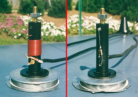
Photo 5. At left, inside the base of the Barjan 11-meter antenna
before modification. Note the white insulating paper between the magnet and
the bottom foil. At right, the antenna base modified for doppler use. After
taking the photo, I added electrical tape to prevent a short from the PIN diode
cathode to the resistor lead.
After unwinding the 11-meter loading coil and removing the matching capacitor,
there is plenty of room to wire in a PIN diode and current limit resistor. To
minimize loss, I shortened the 17-foot coax lines. Remember that for accurate
bearings, all four line lengths must be exactly equal.
Cut each vertical element to one-quarter wavelength, calculated with the
standard formula L = 2808/F where L is element length in inches and F is
frequency in MHz. For the antenna base of Photo 5 above, the feedpoint of the
radiating element is the cathode end of the PIN diode. Taking into account the
length of the whip base and the depth of the hole in the whip holder, the
3/32-inch diameter CB whip I used had to be cut to 16.9 inches to achieve an
effective 19.25-inch quarter wavelength element for 146 MHz. I cut the
leftover rods into whips for the 125 and 70 cm bands. You could also use
3/32-inch diameter welding rod (stainless steel or bronze) to make whips.
I mounted the switcher on the rear panel of the display unit in a 6 X 4 X 3
inch aluminum cabinet (LMB model CR-643), as described in the book (see Photo 6 below).
Components
are on a 2-1/2 inch square of perforated board, copper-clad on the interior
side. The CB antennas came with PL-259 connectors, so I installed four SO-239
receptacles. For UHF, it might be better to convert to BNC fittings for
minimum loss.
Photo 6. KØOV's new Roanoke Doppler antenna switcher mounted on the back panel of
the display box. The two display circuit boards and their connectors are not
installed yet. A short length of RG-58 coax (not shown) ties the switcher
common point to the BNC feedthrough adapter for connection to the VHF
receiver.
I used a Dremel Moto-tool (TM) as a router to insulate the center of the board
where the four single-hole coax fittings mount. This part of the board floats
at +3.7 volts DC, so use care to prevent the coax connectors from shorting to
the box. A "nibbling tool" is an easy way to make a two-inch square hole in
the rear panel to clear these connectors.
A 1-1/2 inch square piece of unclad perf-board fits over the center pins of the
coax receptacles. Four capacitors (C101-C104), four PIN diodes (D101-D104) and
four RF chokes mount on this board. C105-C108 connect between this board and
the isolated return on the copper-clad board. Keep leads as short as possible
on all these components and make sure the path length through D101-D104 and
C101-C104 from common point to center conductor of each SO-239 is equal. Note
the symmetry of the layout in Photo 6 above.
UPDATE: FAR Circuits now sells a printed circuit board for this switcher that is part of the board set for the Roanoke Doppler DF Set. There is an error in the marking on this board. Click here for the correction.
Photo 7. The switcher for mag-mount antennas can be located near the array
instead of in the display unit. N6QAB built his in an aluminum
box. Use care to keep from shorting the +3.5 VDC RF return. (Photos by N6QAB)
Final Thoughts
Be sure that your array "rotates" in the proper direction and in proper
sequence. I numbered the whips from 1 to 4 going clockwise (as viewed from
above the car) beginning with the left front (LF). To minimize the chance of
installation error, I marked the whip bases, coax plugs, and box receptacles
with location designators (LF, RF, RR, LR) instead of numbers.
Optimum spacing of the four array sides is given by the formula D = 2630/F
where D is distance between adjacent whips in inches and F is received
frequency in MHz. This distance is not critical, but use care to place the
whips in a perfect square pattern on the roof and align the array sides
parallel to the sides of the vehicle.
It's tedious to set out the mag-mount whips using just a ruler or tape measure. I made
separate cardboard templates for optimum 146, 223, and 440 MHz spacing.
Cutouts in the template corners match the whip bases. Emplacement is fast and
misalignment is avoided with the templates. Once the whips are in place, I
remove the template so it doesn't get rained on or blow away. Kevin Kelly N6QAB went a
step further and marked the top of his vehicle with whip locations (see Photo 8 below).
Photo 8. (Photos by N6QAB)
When changing bands, check the bearing accuracy of your setup using a known
signal source before setting out to find an unknown emitter. In my case,
readjustment of the calibration control has not been necessary when whip length
is within 20 per cent of resonance. On the other hand, using two meter whips
on 224 MHz gives about 90 degrees bearing error. The presence of other VHF
antennas on your vehicle may cause bearing error on some bands.
Fixed-site VHF doppler antennas usually use vertical dipoles instead of quarter-wavelength whips. Dipoles provide better RDF performance because inter-whip coupling through the ground plane is eliminated. Vertical dipoles are seldom seen on mobiles, because such an array is twice as tall and much less "stealthy" than a whip array. However, Vincent Fiscus KB7ADL built a 4-dipole two-meter array for his mobile (photos below) using this wide-range switcher and he says it works great.
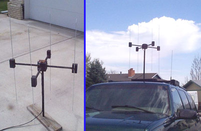
Photo 9. Vincent Fiscus KB7ADL built his two-meter Roanoke Doppler antenna using dipoles instead of quarter-wavelength whips. He reports that weak-signal and multipath performance is better. (Photos by KB7ADL)
This antenna system is suitable for other "hard switched" doppler sets including the Agrelo DFjr, which is no longer marketed. I use it regularly with a MicroFinder by AHHA! Solutions, which is also no longer on the market. It is important to note that whips are switched ON by taking the appropriate logic line LOW. The appropriate MicroFinder V2.0 antenna configuration command is:
asw 4 l
Note that the last character of the command is a letter "l" for LOW, not a numeral one. I obtained +5V from pin 5 of the Microfinder DB-9 antenna connector (always HIGH in the 4-antenna mode) to feed the diodes in the +3.7V source.
Similarly, this antenna system should work well with the Montreal Doppler II by VE2EMM. (Select the "4-" antenna option.)
I haven't tried it, but this antenna system should be a good replacement for the Dick Smith model K-6345 antenna set. The four logic signals from IC6 go to the four antenna logic lines. Since these lines swing positive and negative in the Dick Smith set, the +3.7V supply is not needed. Just connect the 3.7V input (pin 5 of connector in the schematic above) to circuit ground on the control display unit. You will need a 5-wire cable to the antenna unit instead of 4 wires as in the original Dick Smith set.
This antenna system is not suitable for use with "soft-switched" dopplers made by Doppler Systems of Arizona.
If you build this antenna system, please send e-mail to k0ov@homingin.com, letting me know what doppler display you have and how this antenna set works for you.
© 1996 & 2008 Joseph D. Moell. All rights reserved.

 Back to the Homing In home page
This page updated 18 April 2008