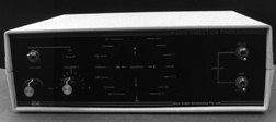

The Dick Smith Electronics (DSE) model K-6345 Radio Direction Finder (RDF) unit has drawn considerable interest among transmitter hunters. The low price of this kit, compared to other commercial Doppler RDFs, has been the main attraction. It has potential applications from six meters to 70 cm for both sport and serious use in volunteer enforcement and search/rescue efforts. It is intended to work with any FM receiver in the appropriate frequency range, including hand-helds and scanners.
I spent several weeks evaluating the DSE unit and comparing it to similar homebrew and commercial Doppler RDFs. I found several deficiencies which were also noticed by other builders of the unit in the southern California area:
As a result, I found the original DSE design was virtually useless for mobile hunting in urban areas because the display dashed around rapidly with no discernible trend. Primary advantages of the Doppler RDF technique over beam/quad/loop schemes are that Doppler sets are easier to use in motion and they average out multipath indications. But this was not the case with the DSE unit because of the aforementioned problems.
Fortunately, there are several ways to improve the unit and make it a credible performer. A few of them have been mentioned briefly, with few details, in an addendum sheet now being supplied with the kit. The remainder, including the fixes to the active filter stage, were developed by the author. The changes are all quite simple and involve little additional cost. They are in two areas, the Antenna Switching Unit (ASU) and the bandpass filter stage.
 Electronic rotation of the antenna assembly happens when each of the four whip
antennas is sequentially switched to the receiver by the ASU. Only one antenna
is connected to the receiver at any instant. The other three are disconnected
by diodes D201-D204 in the ASU and shorted to ground by diodes D205-D208 at the
antenna bases. Because these unused whips are grounded out, they act as
parasitic elements. This adds harmonic content and amplitude modulation to the
induced Doppler signal. The effects of reflections from nearby terrain
features are enhanced by the re-radiation. So even a small amount of multipath
results in unreadable displays when the unit is used in motion.
The solution is to have the switched-off whips be electrically floating instead of grounded. Remove the shunt diodes (D205-D208) at the bases of the four whips and discard. This won't adversely affect the operation of the ASU. I measured 26 dB isolation from each switched-off whip base to the receiver using the shunt diode and 23 dB without it. The difference is insignificant.
The switched-off whips will still appear to be grounded if the coax lines to the ASU are an odd multiple of an electrical quarter wavelength. That's because a non-conducting diode in the ASU is transformed to an apparent short at the end of an odd quarter wavelength multiple line. So for best results, change these lines to be exact electrical half wavelengths at the frequency of interest.
Be sure to take the velocity factor of the coax into consideration in the computation. For two meters, using ordinary polyethylene dielectric RG-58 (66% velocity factor), the coax lengths should be 26-1/2 inches (or a multiple) from the antenna base to the ASU circuit board. This length includes the connector on the box and the lead inside from the connector to the board. For foam polyethylene cables such as RG-8/X (78% velocity factor), the length should be 31-1/2 inches for two meters. It is important that all four lines be of equal length.
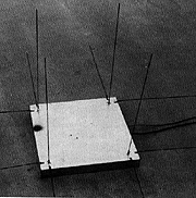
A one-piece antenna assembly like the one in the photo is easy to mount on the roof of a car with suction cups and nylon straps (not shown). This version is made from an aluminum chassis with cover plate on the bottom for shielding. The plastic ASU box supplied by DSE is acceptable if it is inside a larger metal enclosure like the one shown.
Other ways that local hams have configured the antenna system include an open wooden frame with individual ground planes in the back of a pick-up, a set of four vertical dipoles on a PVC pipe support, and four individual magnetic mount antennas on the vehicle roof. In any of these cases, the ASU board should be relocated into a metal box, or else the inside of the plastic box should be sprayed with conductive paint for shielding.
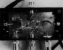 The short leads inside the ASU box from the four coax receptacles to the board
should be changed to equal lengths of small coax, such as RG-174/U, replacing
the bare wire provided. Alternately, when the entire antenna system is in a
metal enclosure as in the photo, the four connectors can be deleted and the
RG-58 lines can go directly from the antenna bases to the ASU board.
A good ground plane for the antenna system is very important. Eight radials are attached to the antenna base chassis with lugs as shown in the photo. The radials and the whips should be stiff enough that they don't flop around when in motion. Bronze welding rod (3/32 inch diameter) is ideal for this purpose. It takes solder readily and is available inexpensively at welding supply stores.
Switching noise from the BA244 diodes supplied by DSE is objectionable. It can mask weaker signals. You'll notice an improvement by replacing D101-D104 with PIN types, such as Motorola MPN-3401. An equivalent part is available in the ECG and NTE replacement semiconductor lines as ECG-555 and NTE-555. These diodes are in low-inductance packages with tabs instead of wire leads, and should be surface-mounted to the etch side of the ASU board.
UPDATE: If you have a K-6345 display unit without the matching antenna set, you may be able to substitute the Wide-Range Doppler Antenna System described in this site.
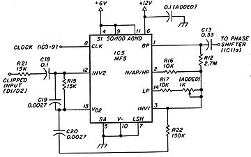
In a properly designed switched capacitor bandpass filter, the response peak is at an exact submultiple of the clock frequency. The filter peak should follow the clock input exactly, so that any drift in the antenna rotation frequency is tracked by the filter. Due to a characteristic of the MF5 filter IC, the peak will be offset by 0.615 per cent if the two 10K resistors (R16 and R17) are perfectly matched.
This good a resistor value match is unlikely with the 5 percent resistors supplied. With unmatched resistors, the offset could be up to ten per cent. In the case of the evaluation unit it was 7.1 per cent. Any offset causes phase changes in the filtered Doppler signal when voice modulation and multipath cause amplitude changes in the input tone level. These phase changes result in erroneous changes of bearing on the RDF display.
Fortunately, it's easy to make significant improvements in the filter section. First, raise the value of R12 from 150K to 2.7M. This gives a filter Q of 270. Next, correct the offset problem by making the resistance at R17 to be 0.615% (about 61.5 ohms) greater than R16.
 Don't try to do this by choosing fixed resistors with a precision ohmmeter.
There's an easier way which makes use of the greatly increased Q of the filter.
Add a 1000 ohm variable resistor in series with R17. Since its adjustment is a
bit touchy, a multiturn miniature trimmer pot is best. Glue it to the circuit
board and wire it in, as it will become a permanent part of the unit. Set this
pot for zero ohms at first.
The pot is adjusted with the control unit hooked up to a completed antenna unit and VHF-FM receiver. Transmit an unmodulated test signal (from a separate transmitter) and measure the filtered DF tone at pin 1 of IC5 (the MF5) with an oscilloscope or AC voltmeter. Slowly adjust the added pot for maximum amplitude of this DF tone. The test signal must be unmodulated and full-quieting or it will be difficult to find the peak. The setting of the pot will depend on how well matched R16 and R17 are. If the level goes down instead of up as the pot resistance is increased, then R17 is already more than 62 ohms higher than R16. In that case, swap resistors at R16 and R17, set the pot to zero ohms, and try readjusting again.
To improve digital noise rejection and minimize the chance of oscillation, filter the Vcc line to the MF5 with a 0.1 microfarad miniature ceramic capacitor. Put it on the etch side of the board at pins 6 and 7 with very short leads.
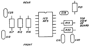
Increasing the value of R12 to 2.7 megohms provides high Q filtering without detrimental effects from clipping in the filter or phase shifter stages. Although unlikely, it is possible that such a high value on some units might upset the MF5 output biasing due to its input offset currents. It could also cause the MF5 to oscillate. If either occurs, lower the value of R12 as required. There were no such problems in my evaluation unit over a wide temperature range. The DC voltage at pins 1 and 14 of the MF5 with no Doppler signal input will be within +/- 1 volt of the DC voltage at pin 11 if all is well.
Be very careful to check that the antenna is electronically rotating in the proper direction. It is easy to get it "backwards" so that the antenna unit and the display rotation are in opposite directions. If the antenna unit is rotating backwards, the unit will have a left/right (90/270 degrees) reversal of bearings when calibrated on a reference signal in front of the vehicle (zero degrees). I have seen this mistake on two kitbuilders' units. The four pin shielded control cable must be wired pin 1 to pin 1, pin 2 to pin 2, etc.
The DSE instruction manual does not show the exact wiring of the four-pin antenna control cable connectors, nor does it show how to check for proper antenna rotation. There are two ways to do this after the unit is completed. When the instructions tell you to connect control cable pins to test point A and observe the 0, 90, 180, and 270 degree LEDs, connect test point A to the whips themselves in succession, not the control cable pins. This verifies wiring of the antenna cables as well as the control unit and ASU. Antennas are numbered 1 to 4 in clockwise order as viewed from the top of the antenna system.
You can also use an oscilloscope to observe that the control pulses proceed from antenna to antenna in clockwise order. Look at the waveform at each whip. It is low (-0.6 volts) when the whip is on and nearly +12 volts when the whip is off. Sync the scope on whip #1 and observe that #2, #3, and #4 follow in proper sequence.
Repeaters or strong base stations that are a mile or more away give better results. The signal should be strong and the path should be unobstructed. The antenna should be in a relatively clear area. For a mobile system, try a large empty parking lot. Turn the antenna unit or drive the car around in a circle to verify that the bearing is reasonably consistent. Again, don't expect super accuracy on this check, particularly if the repeater is many miles away.
For mobile use, the best final calibration is done with the vehicle in motion. Drive slowly down a long stretch of straight and vacant road with a friend a quarter mile or so ahead, transmitting. With the other vehicle keeping pace ahead of you, adjust the calibration control until the top LED (zero degrees) is on. Now pass the signal source -- the bottom LED (180 degrees) should now be on. Doing the calibration while in motion helps average out the local reflections which can throw off stationary bearings.
The calibration control on the front panel allows for correcting the display to match the orientation of the antenna unit. It also compensates for differing phase delays of the DF tone through different receivers. Unfortunately, the control has less than +/- 90 degrees of range. The display can be rotated in 90 degree steps for more calibration range by rotating the antenna connectors.
For example, let's say that with the signal straight ahead, the calibration control swings the indication from 190 to 330 degrees, but can't get it to zero degrees where we want it. The indication can be rotated 90 degrees clockwise by connecting antenna #4 to the D201 input, antenna #1 to the D202 input, and so forth. Now the calibration control covers the range 280 to 60 degrees for a straight-ahead signal, which includes the desired zero degree indication.
Tests by manufacturers of highly sophisticated commercial and military Doppler RDF systems, such as Watkins Johnson, and by long term users such as the US Coast Guard Auxiliary, have shown that even the very best four-antenna designs have significant inherent inaccuracies when used for medium-distance bearings at fixed sites. Parasitic effects in the antenna system can cause an error of up to +/- 5 degrees around the circle when the unused antennas are properly floating or terminated, and far more if they're not. The readout steps are 11.25 degrees, limiting resolution. On top of all this, atmospheric effects cause additional error. This error can be 15 degrees or more, varying with time of day. It is greatest if part of the path is over land and part over water.
Ten degrees of error at 10 miles causes the line of bearing to miss the source by 1-3/4 miles. Triangulation from three high fixed sites 20 miles apart with a +/- 10 degree error margin will produce an area of uncertainty 13.8 square miles in size. This is where the mobile hunters come in. When it comes to pinpointing the source of malicious QRM and gathering credible evidence, there is no substitute for a cadre of mobile hunters who have practiced their skills and become familiar with their gear.
Mobile hunting with any type of RDF setup can be a difficult task when the hider uses sufficient cunning. Competitive hunters using Doppler RDF sets in southern California do not do better, on average, than teams using vehicle-mounted beams or quads. But the ease of use and rapid updating of Doppler RDF setups make them a good choice, particularly when hunting alone or when hunting a mobile jammer. Having high accuracy is less important in a vehicle because the RDF is being used primarily as a "homing" device.
On the other hand, there are situations when a Doppler RDF is not the best choice for the task. If the signal is very weak, the lack of gain and the residual switching noise in the Doppler antenna system will make it hard to get accurate indications. If the hunted signal is horizontally polarized, reflected signals (often vertical) will be emphasized with respect to the direct signal into the vertical whips. Again, it will be much more difficult to get an accurate bearing. In those situations, a high gain beam or quad, properly polarized, is a better choice for getting a high-accuracy bearing on the signal.
Thanks to fellow T-hunters J. Scott Bovitz N6MI and Jorge DiMartino KI6MD for providing information and equipment that assisted in the evaluation and improvement of this unit. Also thanks to the dozens of transmitter hunters in my area who provide challenging hunts for testing of this and other RDF systems.
© 1987 Joseph D. Moell. All rights reserved.

 Go to the Wide-Range Doppler Antenna System page of this site
Back to the Homing In home page
This page updated 17 March 2009