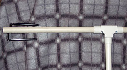
The SlyFox's harmonic filter is on a separate board that mounts at right angles to the main board. The photo was taken before L2 and L4 were spread to 8 TPI.
Description: Two-meter crystal-controlled transmitter with CW and optional voice messaging
I built the Ramsey SlyFox in 1994 and had several problems during the construction and tune-up effort. I have heard from other hams with similar problems, including insufficient output power, high harmonic content, and parasitic oscillations. Still other correspondents have described similar shortcomings with the Ramsey FT-146 transmitter, which uses the same output stages. I had lots of interaction with Ramsey Electronics before I finally got the SlyFox working. I detailed my experiences in a product review for my Homing In column in 73 Magazine, August 1994 issue.
I strongly recommend that all tuning of the FHT-1 and FT-146 be done with an accurate RF wattmeter and a spectrum analyzer. My experience (confirmed by readers and other correspondents) is that if the Ramsey manual's construction and tune-up procedure is followed to the letter, the transmitter may operate in a condition where there is only about 2.7 watts output in the high power mode and the second harmonic is only 16 dB below the carrier. The final transistor runs very hot in this condition. If you use the Ramsey-suggested tune-up method (a light-bulb dummy load tuned for maximum brightness), you may not realize that you have a problem.
The Ramsey manual instructs builders to wind four coils (L2, L3, L4, and L7) on a supplied 5/16X20 bolt and then unscrew the coils. This gives them 20 turns per inch spacing (page 16, steps 84 and 85). As part of tune-up, the manual instructs to spread or compress L3 and L7 to maximize output power (page 25, step 10), but no instructions are given for L2 and L4. However, it turns out that all four coils must be expanded to about 1/8 inch turn-to-turn (8 turns per inch) as a starting point for tuning if the low-power/high-harmonic mode is to be avoided.
By expanding L2 and L4 to 8 turns per inch and then fine-tuning all four air-wound coils and and trimmer C12 very carefully with a spectrum analyzer, I was able to get about 4.5 watts out at 13.8 VDC supply, with all harmonics better than -50 dB and a much cooler final transistor.
Note: A full review of the SlyFox FHT-1 was in Homing In for August 1994. The manual I reviewed was revision 1.2, dated October 1993. To my knowledge, the design and tuneup procedure have not been updated since then. The SlyFox is not in Ramsey's current catalog, but the FT-146 is. If your SlyFox or FT-146 manual has significantly different procedures than I described above, please e-mail me and let me know about it, so I can update this page.
The SlyFox's harmonic filter is on a separate board that mounts at right angles to the main board. The photo was taken before L2 and L4 were spread to 8 TPI.
Description: Phase-sensing RDF adapter for VHF-FM receivers
The following are excerpts from my review of the Foxhound in Homing In for December 1993:
Advertising on the DF-1's manual cover proclaims that it "works with any radio, any frequency." Not exactly. TDOA sets such as the Foxhound require carrier-type signals, such as CW or FM. They aren't designed to track SSB or broadband impulse noise. The receiver used with the DF-1 must have an FM detector. AM and product detector sets will not work with it. Wider dipole spacing is needed below 108 MHz. Portable use of this unit on 80-10 meters is not practical because an effective antenna set would be excessively large.
The Foxhound uses a MF5 active filter IC, which is temperamental about its power source. The design minimum Vcc specified on the MF5 data sheet is 8.0 volts. When the DF-1's battery voltage dropped from 9.5 to 7.8 volts after a short period of use, the MF5 on my test unit went into uncontrollable oscillation. Duracell® specifies end-of-life of a standard MN1604 alkaline battery as 4.8 volts. Thus much of the battery's capacity is wasted by having to replace it at 7.8 V.
I have substituted a series pair of 6-volt Duracell 7K67 batteries in place of the MN1604 battery. These "J-size" batteries are widely sold for replacement in TV remote controls, etc. Each 7K67 has the same ampere-hour rating as an MN1604. Although DF-1 current drain is slightly higher at 12 volts than at 9 volts, the J's last much longer because they can be used to near end-of-life voltage. Performance of the DF-1 is noticeably better on 12 volts compared to 9 volts. The meter circuit is much more sensitive and the left-right indicators flicker less.
The Foxhound has a power jack on the bottom panel. If you don't mind another dangling wire, you can use it to power the board from an external 9 to 12 volt supply. If so, be sure to remove all internal batteries, because the steering diode in series with the battery has been deleted (to raise Vcc to the MF5). If you don't remove or disconnect internal batteries, the external source will attempt to charge them with no current limiting. Damage to batteries or your supply could result.
If you have the original-release DF-1 (circuit board marked "DF4 Rev 1.4 10/12/92"), I recommend upgrading it to the latest circuit for best performance. The early model had problems due to asymmetrical antenna switching, improperly polarized capacitors and inadequate supply bypassing which I discovered during my review. John Ramsey has told me his company will provide instructions for modification on request.
Note: The upgraded DF-1 reviewed here is circuit board revision 2.0 dated 5/13/93. The manual revision is 1.3. DF-1 units now shipping have an even newer board, with National LTC1059CN replacing the MF5 active filter IC (see below). If you have additional experience with this product to share, e-mail me so I can update this page.
Telescoping whips screw into circuit boards at the ends of the antenna crossarms. On my unit, the crimping at the bottom of the whips loosened soon after I began using it in the field. The whips turn freely even though the holding screws are tight in their nuts. Could this be the cause of intermittent indications?
The following e-mail was received from NØFPP in July 2002:
I have a DF-1 Foxhound from about 3 or 4 years ago, but just finished assembly. It is Rev. 2.3.
The Problem: It didn't work.
U2, the MF5 bandpass filter and op-amp combo chip seemed to lose all the signal. All the logic inputs were intact, the 100 kHz from the clock and and 1 kHz from the divider. All other components appeared to be correct, functional and the correct values. Voltages were measured and correct.
Ramsey Electronics' 1st Solution: "Replace U2, the one you have is bad."
OK, this is easier said than done. Ramsey said their supply of the MF5 dried up and that the closest IC they could find was the LTC1059CN. Turns out that National obsoleted the MF5. National Semiconductor specified a replacement, LTC1059CN, the IC Ramsey suggested. Seems no one has this IC except DigiKey. Ordered one from DigiKey. Replaced IC. Still doesn't work. Identical problem to prior problem. Behavior, voltages and signals identical.
Ramsey Electronics' 2nd Solution: "Change the wiring to U2."
Ramsey knew that the replacement IC would need a wiring change, but didn't tell me that when they suggested it earlier. Scott at Ramsey suggested lifting pin 9 from V- (kit's ground) and tying it to the voltage divider that supply the AGND (+4.5V) voltage to pin 4. This ties 9 to AGND instead of V-. According to the MF5 specs, in mode 4 (bandpass) operation, the passband is 1/100th of the external clock when pin 9 is AGND or V-; and the passband is 1/50th of the external clock when pin 9 is V+. However, Scott at Ramsey says that the last of the MF5s and the current supply of LTC1059CN have problems functioning in mode 4 correctly when pin 9 is V-. Scott said to lift pin 9 from the PC board and jumper it to pin 4.
This met with success!
This mod applies to all LTC1059CN and the later MF5 ICs. The mod meets original spec for the MF5, so this mod is worth trying with any similar problem with the MF5. I spent hours on analyzing this problem and this might save someone else some real grief.
Jim Lind NØFPP
The following e-mail was received from GØWEA in February 2005:
I bought a DF-1 kit from a ham store here in the UK. I had a similar problem with antennas in that the method of fitting was poor, so I decided to fit them a different way. Instead of plumbing tubing, I used electrical conduit tubing which has a thicker wall and does not flex like the plumbing type. The 'T' piece is of the inspection type with a plate that can be taken off. If there is ever a problem with the small PC boards, you do not have to mess about trying to access them. You simply unscrew the small inspection plate.
When fitting my antennas, I drilled the holes all the way through with the diameter just large enough for the screw to pass through. Then on the side where the antenna passed through, I opened up the holes to this diameter. When fitting the antenna, you place it in the hole and push the small PC board across to the opposite side. Using a small magnetized screwdriver, you then run the small screw into the base of the antenna and repeat the process for all four antennas.
When fitting my antennas, I also used locking washers. The antennas supplied with my kit do not have the crimped bases. They are solid section, drilled and tapped, and have a joint at the base which allows them to bend over. So by fitting them my way, I was able to line them up with the 'T' section so that when not in use and for storage in the trunk of the car they can be folded over and be parked parallel to the tube and out of harm's way.
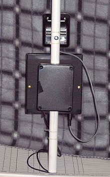
The photo above is one side of the 'T', showing the inspection plate and folded antennas. The photo below is rear of the unit showing the battery box mounted using existing screws for DF1, which were long enough to pass through tubing and battery box case. The battery box holds a battery pack with 8 AA rechargeable batteries.
I had the same problem when I fired it up. The kit came with the MF5 chip. The board is identified with the following: DF-1 REV 2.3 12/17/93. I contacted Ramsey Electronics with no success. After a long wait, I contacted the ham store here in the UK where I bought the kit. They faxed Ramsey and were able to have an LTC1059CN chip sent across, but no official pin-out info. Another phone call produced this info which was the same as on your site. I did a mod on the pc board by cutting a trace which fed two pins, then re-routed with two jumper wires. When building the kit, I used sockets for all the chips so by doing a mod on the PC board I am able to remove any chip if faulty. I tested the unit and it worked better, but heavy current drain on internal battery led me to use a pack of re-chargeable AA batteries.
All seemed ok and ready to use tracking down a local pest. Got a good signal on the culprit and was fiddling with the unit when my pal (who was taking the reading while I got a compass fix) moved his hand on the handle of the DF-1 and accidentally pulled the lead which links the output of the Alinco DJG5 to the DF-1, causing it to come out. I didn't think too much of this until the radio ceased to produce audio. A check showed audio amp blown and just faint audio if held close to ear. We checked the 2.5mm jack sockets supplied with the DF-1 kit and found them to be a poor fit and now may solder leads direct to the PC board.
Rick GØWEA.
Thanks Jim and Rick! Send comments/updates on these mods to k0ov@homingin.com
 Back to "Ramsey" on the Frequently Asked Questions page
Back to the RDF-Related Links page
Back to the Homing In home page
This page updated 21 February 2005