SigTrax for Apple and Android
From my Homing In column in the July 2014 issue of CQ-Plus Digital Magazine
In January 2014, I received e-mail from Jim McCullers WA4CWI, who is a computer software engineer and entrepreneur. In telling me about his new app, he wrote, "I was co-winner in 1982 of the first foxhunt conducted by Birmingham Amateur Radio Club and have participated in many hunts since then, both as fox and hound. I have also been involved with several near-space balloon launches and I succeeded in recovering one where all telemetry was lost and we depended on a 30 milliwatt two-meter beacon to locate the payload.
"I also help in finding interference and have tracked down a pirate broadcaster," Jim continued. "With SigTrax, I combined my enjoyment of RDF and programming to create a solution that eliminates a lot of the burden of carrying maps and drawing bearing lines while attempting to locate a signal."
An important goal for Jim was for his app to work on either Apple or Android devices. He wrote, "I believe an app that is general purpose in nature should not limit itself to a single platform. I have given it an attractive price that, combined with the web site, should encourage people to purchase."
SigTrax iOS version is $3.79 in the Apple Store and the Android version is $3.99 at Google Play. If you cannot find the program, verify that your device has built-in GPS. Upon loading, the program displays map or satellite view, whichever you have selected, with a blue dot indicating your position. GPS coordinates are shown in the upper right.
Like FHP, SigTrax has an internal Compass Rotation mode that allows you to put a bearing on the map by simply rotating your device until the incoming signal indication is dead ahead. Then tap the blue dot that indicates your GPS position. You will get a dialog box that asks if you want to "Insert Fix Bearing?" Tap Yes and the bearing will be added to the list.
SigTrax Map View always shows all bearings at once, drawn in the color selected by Settings. Wherever any two bearings intersect, the program places a red pin. (SigTrax calls the intersections "crosspoints.") Tapping on a red pin pops up a dialogue box with the GPS coordinates of the crosspoint. The box also has an icon which, if tapped, takes you out of the program to Google Maps, where a blue-lined map and directions from your location to the crosspoint are shown.
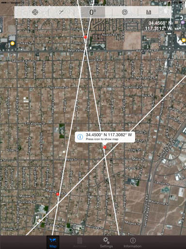
SigTrax puts a red pin at every bearing crosspoint. White bearings show up best on Google satellite view. The traditional "pinch" method zooms the map in and out to show exact locations of the crosspoints.
When I first tried SigTrax, our county RACES organization had begun a monthly cooperative two-meter transmitter hunt to help newcomers gain RDF skills that they could use for search and rescue. During the hunt, participants communicate on a UHF repeater with announcements such as, "I'm at Third and Elm and the signal is due east." I told Jim that it would be nice to be able to enter such a bearing quickly by sliding the map to Third and Elm, tapping it, and typing 90 degrees into a pop-up dialogue box.
When Apple Version 1.3.0 of SigTrax was released in March, that feature was included. Jim told me that it may not be possible in Android because only the Apple OS can distinguish between pressure on the screen and a tap. Also there are differences among Android devices in their responses to varying touch forces.
An extensive Settings Menu allows selection of bearing color, bearing length, measurement units, etc. The maximum bearing length is 10,000 kilometers (6214 miles). SigTrax uses great-circle algorithms for bearing traces, so it can be used for long-distance triangulation like FHP. The red pin is slightly offset from the crosspoint when the triangulation is distant, but it isn't important because of the inherent uncertainty of skywave bearings.
SigTrax includes a method of entering bearings from your location without relying on the internal compass. "The compass technology in mobile devices is not well developed and impossible to keep in calibration," WA4CWI opines. "I tell people that if lost in a forest, I would place the device against a tree and let moss grow on the north side rather than trust its internal compass heading. So I added the Rotation Ring."
If you set Map Rotation to Manual in the Settings menu, the Map View includes a ring near the bottom of the screen and a true heading at the top that corresponds to the map orientation. Tap the right side of the ring to rotate the map counterclockwise and increase the straight-ahead true heading, or tap the left side to do the opposite. The map moves in ten-degree steps, but you can toggle that to one degree or 0.1 degree steps by pressing the center of the ring for about a second. When the map is oriented such that the signal is toward the top, press your blue location dot as before to insert a bearing from your location.
To take SigTrax bearings without using the internal compass, rotate the map in 10, 1, or 0.1 degree steps with the rotation ring at the bottom. Red bearings show up best on Google map view.
I have a higher opinion of the internal compass than Jim does. When I first tried out my iPad with a dedicated compass app (Digital Compass), I agreed with him because the compass heading was inaccurate and would often "stick" as I turned the device, even after performing Apple's "wave in a figure-eight" compass calibration routine. Then I removed the iPad from its Belkin folio case/stand and the compass began working fine. The folio has a magnet closure, but even cutting off the magnet wouldn't get the iPad compass to work while inside it. So now the iPad goes "naked" or in a zip-lock bag when I'm transmitter hunting. Compass performance is excellent most of the time, but it works best when I hold the device parallel to the ground, not "standing up."
Apple makes two iPad Mini models, one with cellular data plus WiFi, and one with only WiFi. Only the cellular-equipped iPads include GPS, because the iPad GPS depends on cellular system data for rapid startup. When I was away from cellular service on the high seas recently, I couldn't get the iPad GPS to acquire my location.
Cellular data plans for iPad are available on a month-to-month basis with no contract from the four major carriers. Even before I signed up, my Verizon version acquired GPS in seconds because it picked up LTE location data from the towers. But for streaming Google Maps in the boonies for the triangulation programs, a cellular plan is a necessity.
SigTrax Plus, DataTrax and TraxTeam
From my Homing In column in the the August 2019 issue of CQ Amateur Radio Magazine.
SigTrax Plus by Jim McCullers WA4CWI has an add-on interface for automatic display and plotting of Doppler bearings on the move.
With no RS-232 or USB ports to work with, getting bearing data into a phone or tablet was a challenge that Jim took on in 2014. He looked into an AFSK interface box to go between the Doppler and the audio input jack, like the Square credit card reader. He also considered feeding data audio into the device's microphone, as is done in some medical accessories. In the end, he decided to transfer the Doppler data via Bluetooth LE. That scheme works equally well with Apple and Android devices. It has the advantage of a wire-free connection from Doppler to SigTrax Pro. The Navigator can sit anywhere in the vehicle.
Commercial RS-232-to-Bluetooth adapters that Jim tested proved to be unsuitable for this project, so he produces and sells his own proprietary DataTrax "dongle" at his Web site. It plugs into the Doppler's DB9 RS-232 port and gets power via USB. (Your new vehicle has USB charging ports, right?)
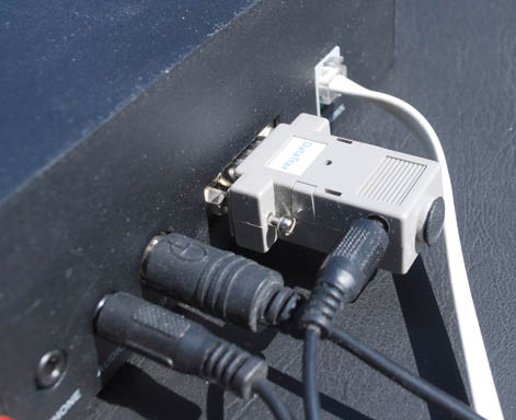
The DataTrax dongle attaches to the DB9 RS-232 connector of the Doppler set and transmits serial data to the phone or tablet via Bluetooth LE. Power comes from a USB connection.
Over the years, several Doppler RDF products have incorporated the Agrelo serial bearing interface including the DFjr by Joe Agrelo, N2OOC (Agrelo Engineering), the DSP-RDF by Dan Welch, W6DFW (SK) and the MicroFinder by Rich Harrington, KN6FW (AHHA! Solutions). None of them are currently in production, but if you find a working used unit, it should be compatible with DataTrax. They all combine the GPS and RDF data into a single serial input to the dongle, although there are differences in the number of positions and bearings sent out per minute.
My favorite of these Dopplers is MicroFinder because it includes second-harmonic detection of the Doppler tone to help filter out reflected bearings. It also can be set up to send single bearings to the mapping program at the touch of a button. My first test of the SigTrax Pro serial interface was with the Microfinder and a Magellan Meridian Gold GPS. That was successful, so the next step was to test with a Doppler that readers can readily purchase.
The only Doppler sets with Agrelo-format output now being marketed are designs of WB6EYV. Bob sells his PicoDopp through his company, Doppler DF Instruments. It comes to you as a set of assembled and tested circuit boards that you will need to wire together and mount in the enclosure of your choice. If you have built electronic kits and can handle the packaging details, Bob's extensive documentation should get you the rest of the way.
In 2011, WB6EYV licensed his PicoDopp design to Global TSCM Group, which sells it as the DF2020T kit. It's not quite plug-and-play because some minor assembly is required. All you will need is a screwdriver. Simply mount the processor, display and connector boards into the pre-drilled box, attach four whip antennas of appropriate length to the magnetic-mount bases, and you're ready to go mobile. MFJ sells the same Doppler set as model MFJ-5005.
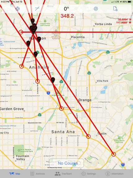
In order to plot bearings relative to true north, SigTrax needs to know the vehicle heading. The most accurate way to determine the vehicle's direction of travel is with GPS, but the vehicle must be moving at least 3.5 MPH. When the vehicle is stopped or moving more slowly than that, "No Course" appears at the bottom of the screen.
To map Doppler bearings when the vehicle is stopped (at the hilltop starting point of a T-hunt, for instance), switch to the STATIC mode in the SETTINGS menu and enter the vehicle heading manually. SigTrax will make the appropriate heading correction. Switch back to the MOBILE mode for bearings as you drive.
When Doppler bearings are being received by the program and the vehicle is moving, they are displayed in the map view at a rate determined by the SAMPLE INTERVAL setting. When RECORDING is off, bearings are displayed but not saved. When RECORDING is turned on (red dot flashing), these bearings disappear and a new set of bearings begin to appear. The details of these bearings go into a list that can be saved in an archive file. Later, the file can be recalled, edited, and added to newer bearings.
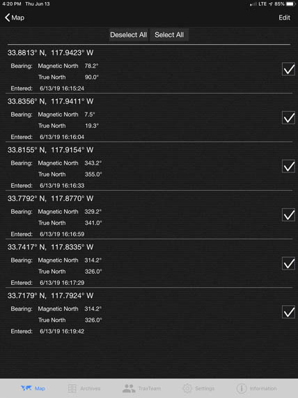
The list of bearings can be viewed and edited. Bearings can be added to and deleted from the list. They can be saved in archives and shared with other foxhunters.
It's important to spend some time optimizing the three DataTrax adjustments in the SETTINGS menu: SAMPLE INTERVAL, SMOOTHING LEVEL and COURSE DELTA. SAMPLE INTERVAL selects the bearing plotting rate over the range of every second to every 60 seconds. SMOOTHING LEVEL and COURSE DATA control how the bearings are averaged and how sudden changes of vehicle direction affect the displayed bearings. When you're starting out and tracking a steady signal, the sample interval should be 30 to 60 seconds, unless you think you are very close to the transmitter.
In some situations, continuous plotting will cause confusion. Examples are a foxhunt with multiple transmitters on the same frequency or when hunting on a repeater input with numerous users. It may be better to plot bearings on the target by turning RECORDING on and off. To minimize screen clutter and to get the best bearings for triangulation, try to map them only from high locations when the signal is clear with a minimum of multipath flutter.
This discussion of Doppler sets and bearing mapping wouldn't be complete without a few words about accuracy. A well constructed and installed mobile VHF/UHF Doppler set will give good bearings most of the time, especially when the target signal is only a few blocks away. But just because your Doppler's serial output is in decimal degrees or even tenths of a degree, don't fool yourself into thinking that your bearings with it are that accurate, especially when the target isn't line-of-sight. Hills, buildings and other large objects in the path can easily cause significant bearing errors. Bearings to targets across bodies of water are subject to error due to refraction effects.
A good rule of thumb is to assume that Doppler bearings taken under ideal conditions are accurate to five degrees, plus or minus. A five-degree error at 11.5 miles distance causes a line-of-bearing to miss the target by one mile.
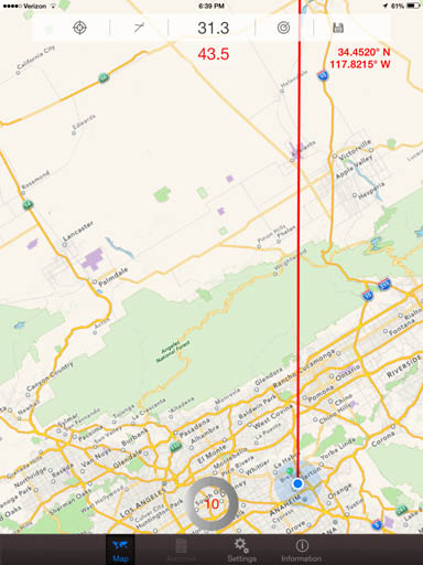
For a near-worst-case example, the screen below shows bearings on the output of a two-meter repeater that was 45 miles away with intervening hills, as I drove freeways and surface streets. The inconsistencies in the plotted bearings are easy to see. There are even a few "wild" bearings that could have been caused by large trailer trucks passing by. It's clear that the signal source is far away and the crosspoint icons are not triangulated fixes.
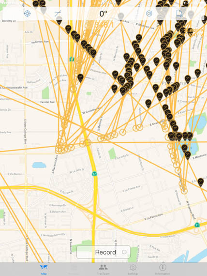
First test of the SigTrax and MicroFinder combination on the road map view. The sample interval is short, resulting in a large number of orange bearing lines that show the normal variations in Doppler bearings from a moving vehicle.
The screen below shows mobile bearings under better conditions.
A series of red mobile bearings taken over flat terrain en route to a hilltop fox. Bearings were recorded in clear locations at key intersections as the transmitter was approached from the southeast, south, and then west. Most of the crosspoints are in or near the park where the transmitter is located.
SigTrax Plus is available for Apple and Android devices. It works with iPads of Generation 2 and later. Internal GPS and an Internet connection for map updating are required. Also available as a SigTrax add-on is TraxTeam. Registered users of TraxTeam can form teams to share bearings in real time as they privately collaborate to find the sources of signals.

From my Homing In column in the July 2014 issue of CQ-Plus Digital Magazine
Charles Scharlau NZ0I discovered hidden transmitter hunting in the Puget Sound area of Washington State in the 1980s. He went on to compete in the first USA Amateur Radio Direction Finding (ARDF) Championships in 2001, which led to a trip to the Czech Republic in 2004 as a member of USA's team for the World Championships. Charles and his wife Nadia KO4ADV have continued their involvement in ARDF as much as family obligations have allowed. They have been course planners and setters for numerous USA ARDF Championships near their home in North Carolina beginning in 2013.
Charles is a software engineer and embedded systems specialist who has formed his own company, Digital Confections. He is the proud author of the new Map-n-Compass app (MnC). It sells for $9.99 and is only available for Apple devices. MnC is so feature-rich that you will spend a lot of time learning how to use it. Charles must have realized this, because upon loading, the first dialogue box asks if you want to go to the map or to the 44-page help file.
Like the other two apps, MnC will go along on a hunt with you, keeping track of your position, plotting your bearings and providing estimated transmitter locations based on triangulations. Charles intended the app to be used for all-on-foot hunts under international rules, but there's no reason why it can't also be used on area-wide mobile hunts, provided that you go into the settings and increase the maximum bearing length as appropriate.
An advantage of MnC is that it is designed for multiple-transmitter hunts and will keep track of bearings for up to five different foxes at a time. In the screen shot of a sample mobile hunt, the timing is stopped and all bearings are displayed with different colors for each fox. When the hunt clock is running, bearings for only one transmitter at a time are shown. The program draws a purple trace as "bread crumbs" showing your route.
MnC is intended to be used with orienteering maps that have been created in accordance with International Orienteering Federation (IOF) standards. However, it also works with open-source street, aerial and topographical maps, either online or stored on-device. For this illustration, the base map is open-source 4U Outdoor Map. 4U also has a street map version which would be a better choice in urban areas.
MnC not only helps you win transmitter hunts, it creates them. In as little as five minutes, the program can lay out a complete five-transmitter course for ARDF with GPS coordinates for each fox. According to Charles, "I wouldn't want to try designing and field checking courses without it. We carry all of Nadia's courses and Backwoods Orienteering Klub maps in the app, and we use it to help us navigate quickly and easily to all the transmitter locations when we put them out."
I think the coolest MnC feature is its ability to provide a virtual on-foot foxhunt experience with all of the fitness benefits and none of the transmitting hardware. Have a friend create an ARDF course map in the device for you and tell MnC to hide the foxes, so you won't know where they are. Then take the app, plug in your earbuds, go to the start point and switch to navigate mode. Slide the navigation arrow to display "#1-MOE."
You will hear the first virtual transmitter. Hold the device level to the ground and turn in azimuth for the strongest audio signal, just as you would with a two-meter beam. Tap the navigation icon to put a bearing on the screen and move in that direction. Move on while taking bearings until you get within 20 meters of the hidden fox icon, whereupon the program will automatically declare that you found it.
You can then switch to "#2-MOI" and continue on to find that one with virtual RDF, and so on. After finding #5-MO5, you can navigate to the finish by selecting "F" and homing in on the MO signal, or just use map navigation to the double circle. Tap "STOP" and the app will create a record of your course with your GPS track and time to find each fox.
What a great way this is to practice your bearing-taking and navigation skills in between your local ARDF events! As in regular ARDF, your results will be better if you check bearings on all foxes at the start, then choose the order of finding the five foxes to minimize your travel time. MnC's virtual ARDF is easier than actual ARDF in the Beginner mode because all five foxes are continuously transmitting on separate virtual "frequencies" so you can easily tune among them. When you have mastered Beginner mode, switch to Intermediate and Expert, where the foxes are on for 60 seconds each in sequence, just like championship courses.
According to Charles, "Menus should be left in restaurants," so there are no pull-down menus. All functions are accomplished by single-tap, double-tap, or tap-and-slide. This is faster and easier when you are out in the field, but it requires practice and experience to memorize the function commands before you go.
I have become a big fan of this app, but for me it had a long learning curve because of the number of features and the lack of menus. I spent a lot of time switching back and forth between the app and the help files to figure out what to tap, hold or swipe to make it do what I wanted.
There are still many features that I haven't tried yet, such as the ability to create an ARDF course on PC or Mac and send it to MnC by e-mail or iTunes file sharing. Similarly, courses created within MnC can be shared and viewed on PC or Mac. Hunt results files can be displayed and animated to "relive" the hunt experience. You can choose the display orientation, portrait or landscape. Settings can be customized for the number of transmitters, on-air time for each, antenna beamwidth, signal tone pitch, peak versus null signal tracking, arrival range and much more. This app is going to keep me busy for a very long time.
From my Homing In column in the Winter 2012 issue of CQ-VHF Magazine
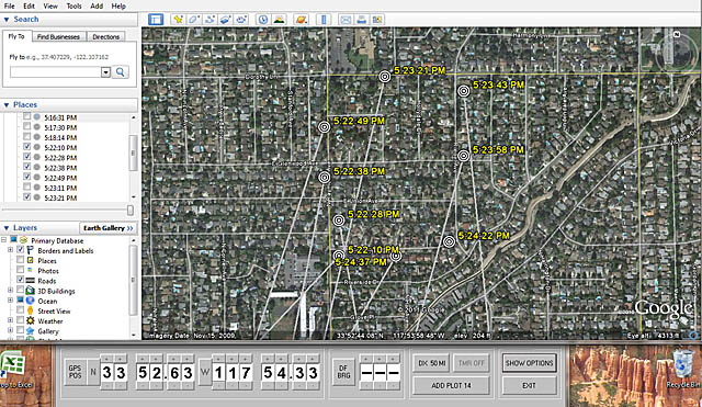
When I tested PocketAPRS for PalmOS a few years ago, I concluded that the screens on hand-held devices are too small for a driver to use successfully on mobile hunts. Better for that is a laptop PC screen and the free GoogleHunt program by Bob Simmons, WB6EYV of Santa Barbara, California. It runs on Windows in tandem with Google Earth and provides a very simple interface between that program, a GPS unit, a Doppler RDF set, and the user. GoogleHunt does this by generating KML files that GoogleEarth parses and displays. The GPS and the Doppler make it automatic and hands-off, but bearings and locations can also be entered from the keyboard.
I tested GoogleHunt with a Magellan Gold GPS unit and a MicroFinder Doppler set. GPS-friendly Dopplers such as MicroFinder receive coordinates, direction of travel and velocity in NMEA-0183 format from the GPS at 4800 baud. They then send this data on to the PC, interspersed with RDF bearings in Agrelo format (see above).
I made the GoogleHunt plot in the illustration below as I drove the streets in my neighborhood and the MicroFinder took bearings on an active repeater output frequency. On the map, each bearing has a "target" at the location where it was taken, a time stamp, and a line indicating the true (relative to north) bearing. Below the overhead view is the GoogleHunt console showing current latitude, longitude and bearing in degrees. When serial data isn't streaming in, the up/down arrows on each digit can be used to manually update these values.
GoogleHunt can display up to a hundred locations and bearing lines at a time. The ADD PLOT button keeps track of the number of bearings. The DX button selects the length in miles of the bearing lines. Unwanted bearings can be suppressed by going to the CURRENT HUNT file under PLACES in the Google Earth console.
In the TIMER mode, GoogleHunt can be configured to automatically generate bearing plots at intervals of one, two, five or ten minutes when location and bearing data is available. That might be convenient when you're driving alone and tracking a steady signal. However, there are many situations where this could cause confusion, such as a foxhunt with multiple transmitters on the same frequency or a repeater input with numerous users. I prefer commanding each bearing plot manually by hitting the space bar on the computer. To avoid screen clutter and to get the best bearings for triangulation, I try to plot them only from high locations when the signal I'm tracking is coming in clearly with a minimum of multipath flutter.
Google Earth fetches satellite images from the Internet and stores them in your computer's cache memory for fast retrieval. This means that a live Internet connection in the vehicle is not needed for GoogleHunt, provided that Google Earth on that PC has previously "visited" the area where you are doing RDF. In the lower right corner of the map is the eye level, which is 4313 feet in this case. To view street names, the eye level must be less than about 5000 feet. Viewing of cars, driveways and similar details requires an eye level of 1000 feet or less.
Before setting out on a transmitter hunt or RDF mission, run Google Earth with a fast Internet connection at the lowest eye level you will need. (GoogleHunt does not need to be running with Google Earth for this.) Scan over the entire area of the hunt slowly enough that all the images load. This will put them into your computer cache at the maximum resolution you will need for hunting.
Bob has put a lot of work into making GoogleHunt easy to use. The hardest part for me was installing a RS232-to-USB adapter on the Windows PC and finding the right COM port. Then it was merely a matter of configuring my Doppler for an optimum rate of position and bearing updates. There was some trial-and-error to this task because GoogleHunt won't plot bearings when the vehicle is stopped or moving at less than 3 knots. Usually that's good because GPS units don't report accurate headings at very low velocities, but an override of that feature for testing would be nice.
I regularly receive requests for information about linking together RDF systems at several stationary sites for automatic triangulation. The newest software product from WB6EYV can do that via the Internet. Bob's DoppSite program enables remote viewing of RDF stations on a Google Earth maps. The program can drive multiple displays and each display can plot multiple sites, making an area-wide RDF network possible.
With DoppSite, a Windows PC, an Agrelo-format RDF set and a fast Internet connection, you can generate a Web site that sends bearing plots on Google Earth maps and updates them as often as once per second. Bearings taken at your site can be continuously viewed by other Google Earth users with Internet connections. Whether your site is public or private is merely a matter of how you distribute the access information for it.
DoppSite Web stations can be viewed from any Internet-connected computer running Google Earth, but it is intended to operate only at fixed RDF stations. You will need to provide the static IP address and port number of your DoppSite computer for others to access it. Your service provider may be able to provide an unchanging IP address or you can utilize a DNS management service such as No-IP, as Bob explains in his extensive documentation.
Bob Simmons is an amazingly prolific hardware designer and software writer. In addition to the products I have described above, he has made several bearing display programs available at no charge. They include WinDopp PC, which receives the Agrelo-format stream and paints a series of headings in polar format on Windows PCs. There are versions of this program for old MS-DOS computers with RS-232 ports (PicoDopp PC) and for PalmOS devices with infrared interface (FoxPlot PDA). They can be used in place of a LED display board in a PicoDopp system.
International rules forbid the use of GPS positioning and electronic mapping by participants in formal ARDF championship contests. National and world-class radio-orienteers are expected to do it the old-fashioned way, with paper maps supplied by the course-setters and their own hand-held compasses. Don't be surprised if the organizers of championship ARDF events forbid the carrying of any mobile devices on courses from now on.
I look forward to hearing from you about your transmitter hunts, including your experiences with new tools such as these apps. When you experiment with computer mapping and tracking, keep safety in mind at all times. On mobile hunts, get a helper to handle the computer and RDF gear when you drive, or get someone else to drive so you can concentrate on the RDF task. Have solid mountings for your computer, GPS and RDF gear so they can't fly about during sudden stops. Minimize distractions and pay full attention to the road while driving. Take your time and have fun!
© 2012, 2014, 2019 and 2025 Joseph D. Moell. All rights reserved.
Back to the Homing In home page
This page updated 4 May 2026
Map-n-Compass
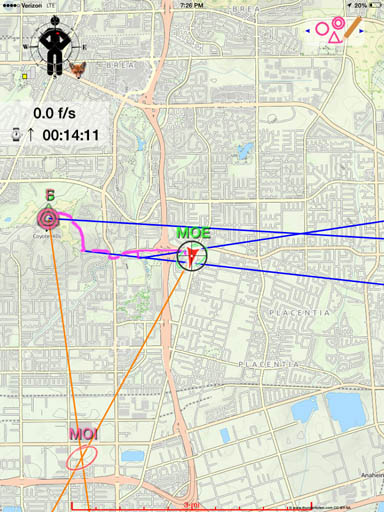
Map-n-Compass in use during a mobile transmitter hunt, starting from Coyote Hills. After 14 minutes, the first fox (MOE) has just been found with three bearings and two additional bearings have triangulated the possible location of the second fox (MOI).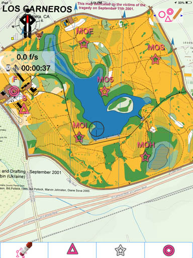
ARDF course-setters can quickly design courses like this within the Map-n-Compass app and then use the device to locate and set the transmitters in the field. The map is oriented to magnetic north, which is standard for ARDF. The five transmitter icons can be hidden for assisted or virtual tracking.GoogleHunt and DoppSite
Connected to a MicroFinder Doppler set, GoogleHunt plotted this series of bearings to a distant repeater along streets in my neighborhood.Final Thoughts
 Go to the Homing In magazine column index