1. Pins 6,7,and 8 of U3 are tied to U12-12 instead of ground
2. Incomplete trace from a 5V jumper to U3-16 (first board)
3. Incomplete trace from U2-8 to C19 (second board)
4. Collector of Q1 tied to U5-5 instead of 5V.
5. No ground on U4-4 and bottom R-17 (tied together but going nowhere)
6. C1 stenciled as C10
7. C22 and C25 stencilling reversed
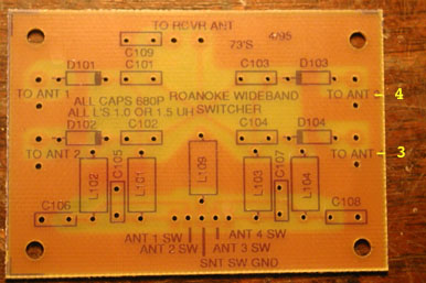
Rick Ching KH7O reported the following problems on a FAR Circuits Roanoke board he purchased at the Dayton Hamvention in the late 1990's.
1. Schematic U2d is U1d on board
2. Schematic U1d is U2d on board
3. U1 trace between P13 & P14 shorted
4. R32 and R30 junction missing 5v, correct by connecting to +5v
5. U3 Capacitor on P1 going nowhere, correct by jumpering to similar cap on U3-2
6. U3 Capacitor P4 jumper to cap on P5
7. U4-1 connect to gnd
8. R9 is 22K, not 22 ohms
In addition, on the Display board, the LED anode ring was missing pads for the 56 ohm resistor.
Please send e-mail to k0ov@homingin.com if you have more information on this board.


 Back to the Hardware Sources page
Back to the Homing In home page
This page updated 20 March 2007