Better Performance from Your Doppler Set
As I explained in previous installments, any factor that causes the strength of the signal at the receiver input to vary as a Doppler array is electronically "rotated" will result in the bearing display being jumpy, hard to interpret and perhaps even downright unreliable when used in a moving vehicle. Unwanted amplitude directivity can be caused by improper positioning of the array on the vehicle, mutual coupling among the elements, improper feedline routing and termination impedance (loading) of switched-off elements in the array.
by Joe Moell KØOV
How bad are these directivity-induced fluctuations? They would be hardly noticeable if there were no terrain features or objects to reflect the signal. But such an environment rarely occurs. Almost anywhere that you are likely to drive, there will be a plethora of these reflected signal sources, commonly called "multipath."
For a given amount of multipath, the effect on a particular Doppler installation depends on a number of factors including the receiver's IF filtering and discriminator performance. The sharpness of the audio bandpass filter in the Doppler display unit also plays an important part. Observing the fluctuations by eye under varying terrain conditions isn't a very scientific way to compare Doppler arrays. It's much better to test in a consistent environment and to record the actual fluctuations. This isn't difficult if the Doppler set has serial directional data output.
There are several formats for serial bearing data streams. Perhaps the most popular at present is the "Agrelo" format, named after the manufacturer of the DFjr Doppler set introduced in 1996. In this format, the 360-degree azimuth range is described by 256 bits, each bit representing about 1.4 degrees. Format is "%xxx/y" where xxx is the relative bearing rounded to the nearest degree and y is the quality of the bearing. Quality is a computed function of the spread of the data points in the sample period and ranges from 1 (worst) to 8 (best).
No More Splattered Bearings
Years ago, tests like this would be done with data plotted on an analog strip-chart recorder, complete with a motor, pens, ink, and special paper. Nowadays it's simple (and much less messy) to let a PC or PDA do the work. Figure 1 below is a PC-generated "strip chart" of a stock DFjr's bearing fluctuations along a test track as taken by Mike Musick NØQBF. Mike and I have experimented with and corresponded about various Doppler arrays over many years.
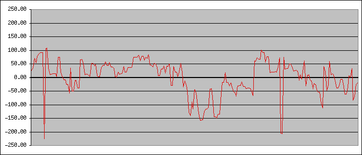
Figure 1. NØQBF's chart of bearing fluctuations along a 5-mile test track with an unmodified mag-mount Doppler array as supplied with the DFjr RDF set. His software plots the difference between displayed bearing and actual computed bearing at 200 points along the route. (Courtesy NØQBF)
I don't know the details of Mike's test track, but it's probably similar to mine. There are two that I use to test two-meter Dopplers and other VHF and UHF RDF sets. Both are conveniently located here in Fullerton and make use of local repeaters. Each is about two miles from the repeater and is about a mile long. In either case, I drive directly toward the repeater's transmitting antenna, observing bearing indications on the repeater output signal. One track is in a suburban business area with the repeater antenna visible in the distance. The other is on a residential street with the repeater tower obscured by a rise in the road.
For calibrating mobile Dopplers and for observing their readout accuracy and steadiness, your vehicle must be in motion. This increases the effective baseline of the antenna system by averaging the fluctuating indications, either by eyeball or by averaging circuits in the Doppler set. When moving directly toward the test signal, it's easy to calibrate the display for a straight-ahead indication.
There is a lot of bearing fluctuation in Figure 1, suggesting that Mike's stock DFjr array was directional in amplitude -- not good. He had already selected his vehicle roof mounting and optimized his cable routing for non-directivity, so he became suspicious of the RF path for the counterpoise on the DFjr's supplied antenna set.
NØQBF wrote, "With each new generation of whips, Agrelo Engineering improved electrical contact between the coax shields and the magnet covers. But the magnets themselves are nonconductive and there are vinyl covers on them to protect the vehicle's finish." Mike realized that this resulted in very little RF coupling from the shields to the ground plane provided by vehicle roof. Most mag-mount antenna suppliers cover the magnet with grounded foil to provide capacitive coupling to the vehicle body (see Photo B), but this was not done on DFjr arrays.
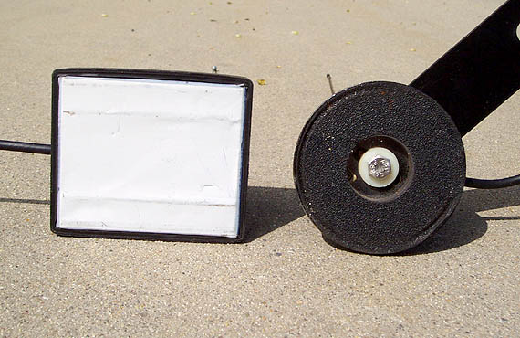
The Larsen mag-mount antenna base at left has a metal foil bottom to provide RF capacitive coupling to the car body. There's no foil on the stock DFjr antenna magnet at right. (KØOV photo)
NØQBF disassembled his array and sandpapered the paint from the magnet holders. Then he covered them top and bottom with copper foil shielding tape (#1181 from 3M Company, which has conductive adhesive). He ran the test track again and got the results of Figure 2 below.
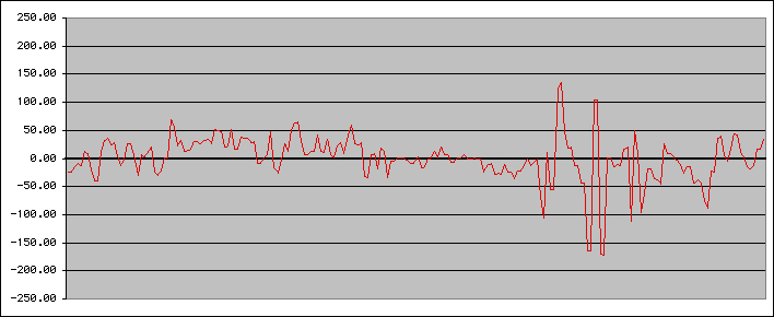
Figure 2. Plot of DFjr array modified with copper foil tape to increase capacitive coupling through the magnets to the metal vehicle roof ground plane. (Courtesy NØQBF)
What an improvement! The original array had errors of greater than 50 degrees a significant percentage of the time and a region of 100 to 150 degrees error. The modified-magnet array was less than 50 degrees off all the time, except for a couple of short flickers. If you saw the predicted amplitude directivity pattern of a Doppler array with reactive termination in part 5 of this series, this won't come as a surprise. A capacitance meter check showed Mike that his mod had reduced the series reactance in each whip base from 10 ohms to about 2 ohms.
Analysis of Figures 1 and 2 showed improvement in standard deviation of the bearing error from 63 degrees to 41 degrees, but Mike wasn't satisfied. He wondered about the aluminum crossarm that holds the DFjr whips in position and provides mounting for the RF switch box. Could it create unwanted coupling between the whips and thereby produce amplitude directivity?
Mike removed the crossarm, carefully positioned the whips on the vehicle roof without it, and drove his test track again. Results were encouraging, so he fabricated a replacement crossarm from ABS plastic. With the whips and switch box mounted on it, he drove his test track and got the plot of Figure 3 below. Bearing fluctuations beyond 50 degrees were rare, even in the heavy multipath area near the end of his track.
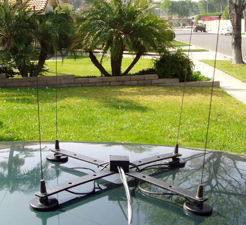
This DFjr antenna array has been modified with a NØQBF one-piece ABS plastic crossarm to replace the stock aluminum arms (but not foil magnet covers). As in the original arms, there are holes for placement of the whips for the 2m, 125 cm and 70 cm bands. Separate quarter-wavelength whip sets for each band insure that the antenna elements are near resonance.
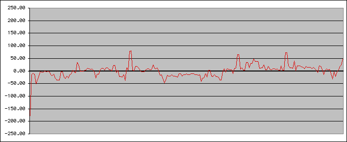
Figure 3. Eliminating the aluminum crossarms in addition to increasing the capacitive coupling produced astonishingly better multipath performance in the DFjr. (Courtesy NØQBF)
"Standard Deviation is now down to 24 degrees," Mike wrote. "The cumulative changes are really evident on APRS map plotting. There is a little wobble from the multipath, but my old 'splattered bearing' problem has completely gone away."
Is that the best this array can do? Probably it is, because the DFjr's RF switcher uses monolithic RF preamps with nominal input impedance of 50 ohms. I showed in the last installment that this termination results in 5 dB amplitude directivity in the best case. Mike is now experimenting with a switcher design using Hittite monolithic RF switches to eliminate the 50-ohm termination of switched-off whips. The dual PIN diode switch circuit in this Homing In site is also a good choice because it provides high-impedance termination of switched-off whips, giving directivity of 1.6 dB or less.
Check Your Mag-Mounts
How good is the coupling and symmetry of the ground plane in your mobile Doppler array? If it has mag-mount whips, verify that there is conductive foil covering the magnets. If not, add foil tape as NØQBF did. Make sure that the coverage is complete and that the foil or tape is firmly connected to the coax shield. Any wrinkles in the foil will decrease the capacitive coupling. Not only must the coupling be excellent on each magnetic base, but the base-to-vehicle capacitances of each one must be equal if unwanted directivity is to be avoided. After any modifications to your Doppler array, be sure to recalibrate the system, just as you should do when you change receivers, vehicles, or ham bands.
Dipole elements ought to provide better RDF performance than quarter-wavelength whips because there would be no inter-element coupling through the ground plane. Vertical dipoles are seldom seen on mobiles because a dipole array is twice as tall and much less "stealthy" than a whip array. But fixed-site VHF Doppler antennas usually use dipoles. For a home-based Doppler, consider an array like the one below by Vincent Fiscus KB7ADL. He used the wide-range antenna switch circuit in this Homing In site. For best possible whip isolation, I recommend placing a ferrite balun at the feedpoint of each dipole.

For fixed installations, a Doppler array of dipoles helps minimize coupling between elements. This one was built by Vincent Fiscus KB7ADL. (Courtesy KB7ADL).
If your Doppler's self-test features include stepping the RF switcher to each whip individually, as does the DFjr, you can perform a quick-and-dirty check of array directivity. While monitoring through the array a steady but not very strong signal, such as a distant repeater, observe the S-meter readings as the array is stopped on each whip in turn. If there are significant differences in signal strength on one or more whips, you have unwanted directivity due to array placement, ground plane or termination issues. Another possibility is a failed component in the switcher. Some users have reported preamp failures in DFjr arrays caused by static discharge. An even more likely cause of preamp or PIN switch failure is accidentally transmitting through it.
So what has happened to the DFjr? The idea of an inexpensive processor-enhanced Doppler set with serial data output for APRS was quickly and enthusiastically embraced by hams, but technical and production problems kept the flow of finished units down to a trickle. Finally in late 1998, Agrelo Engineering closed its doors and disappeared, leaving buyers high and dry. NØQBF and I were soon inundated with inquiries about the company that we couldn't answer because we didn't know the answers ourselves. Mike compiled a Web page of advice for owners of DFjrs and those who may find a used one on sale. You can read Mike's DFjr Advice Page from the "Wayback Machine." Also see my Using and Improving the Agrelo DFjr Doppler Set page in this Homing In site.
Since this series was published, other inexpensive Doppler sets with Agrelo-format data output have come and gone. They include the MicroFinder by AHHA! Solutions, the DSP-RDF by Dan Welch W6DFW (SK), and the DDF2020T by Global TSCM group (same as the MFJ-5005). Perhaps you can find a used one at a ham radio swap meet. Still available, and highly recommended, is PicoDopp by Bob Simmons WB6EYV (Doppler DF Instruments). Bob sells assembled and tested circuit boards so you can create a custom Doppler to suit your needs. For best results, follow the suggestions in this series as you build and install your mobile antenna system. Happy hunting!
 Text and photos © 2004 and 2025 Joseph D. Moell. All rights reserved.
 Back to
Doppler Series, Part 5
Back to
Doppler Series, Part 5
Back to the Homing In home page
This page updated 27 April 2025