Doppler Antenna Design Secrets
My last installment explained the importance of a VHF/UHF Doppler antenna array being as non-directional as possible. Although it may be counter-intuitive, it's true that any factor that causes the amplitude of the received signal to vary as a Doppler array is electronically "rotated" will result in the display being jumpy, hard to interpret, and perhaps even downright unreliable, especially as the vehicle moves through areas of signal reflections.
by Joe Moell KØOV
Undesirable amplitude variations in a Doppler antenna array can have many causes. Last time, I demonstrated that mounting the array (or any other VHF communications antenna) on the corner of a vehicle roof results in at least 4 dB amplitude variation around the azimuth circle, compared to placing it in the center of its counterpoise. Putting it on a blocked surface such as the hood or trunk is far worse. Even if you mount it right in the middle of an unobstructed ground plane, other VHF/UHF antennas in proximity can "pull" the directivity of your array.
Even more important, yet more often overlooked, is the significance of non-directivity in the entire assembly of whips or dipoles. In the examples to follow, I'll assume a 146 MHz array of four quarter-wavelength vertical whips with typical spacing, as in the photo below. But the principles apply to arrays of more whips, and for other VHF/UHF bands.

Many Doppler builders choose a one-band antenna array like this one for two-meters used by Louis Tremblay VA2JX of Montreal. It has four quarter-wavelength whips in an 18-inch square pattern on a metal plate, plus eight radials to provide a symmetrical ground plane under each whip. The one-piece assembly mounts quickly and the whips are always perfectly spaced and aligned.
Figure 1 below is a simplified schematic of the antenna switcher section of a typical Doppler set of the early 1980's, the Dick Smith Electronics (DSE) Model K-6345 from Australia. Series diodes D1-D4 are located on a circuit board in a plastic box, intended to be affixed to the vehicle roof with a suction cup. Wire lengths from each series diode to the common point are exactly equal, about one inch. Separate coax cables, each about 30 inches long and all four equal in length, go from the switcher to the vertical whips. At each whip base, a shunt diode (D5-D8) is connected from the whip base to the ground plane and coax shield.
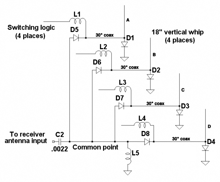
Figure 1. Simplified schematic of the Dick Smith Doppler RF switcher section. Inductors L1-L5 are RF chokes.
To turn on each whip in sequence, a negative logic voltage is impressed through the whip's RF choke (L1-L4) such that its series diode is forward biased (on) and its shunt diode is reverse biased (off). At that instant, the other three whips get positive logic voltage to bias their series diodes off and shunt diodes on. So whenever Whip A is switched into the receiver, whips B, C, and D are switched out and grounded by their shunt diodes, and so forth. The logic voltages are switched in sequence at an audio rate to perform the electronic rotation of the array.
In my tests on real-world signals, the DSE K-6345 display was scrambled most of the time as I drove along. Part of that was due to inadequate damping in the audio filter and phase detector stages, but I was convinced that the antenna system deserved much of the blame. It did, as you can see from analysis of the array using EZNEC, an antenna modeling computer program for the PC.
For simplicity, my model was an array of four quarter-wavelength elements in an 18-inch square pattern over a perfect ground plane at an instant in time. One whip goes to the feedline and the others are grounded, as they are in the K-6345. Sure enough, the effect of those turned-off whips tied to ground by diodes is to create a multi-element parasitic array that is highly directional in amplitude, as Figure 2 below shows. Gain of this array varies more than 11 dB around the azimuth circle. As it is electronically rotated, incoming signals and reflections undergo huge undesired amplitude jumps, in addition to the desired phase jumps.

Figure 2. ELNEC azimuth pattern plot of a 4-whip Doppler array with three whips grounded and one connected to the feedline. The large lobe is in the direction of the active whip, which is in the lower left of the array.
To prove that the shunt RF diodes are the cause of the amplitude directivity problem, simply change the EZNEC model such that switched-off whips are "floating" with no connection to the ground plane, as they would be without the shunt diodes. That gives the excellent pattern of Figure 3 below. There is just 1.3 dB variation around the azimuth circle, which is almost insignificant. Could this be an approach to the perfect Doppler array? Yes, but if the shunt diodes are simply deleted from the circuit of Figure 1, we won't achieve it. That's because the switched-off whips "look back" into an uncontrolled length of coax cable terminated in an open circuit (the switched-off diodes D1-D4).

Figure 3. The undesirable lobe disappears and a nearly perfect circular pattern with no phase anomalies is achieved when the switched-off whips are open-circuited to minimize parasitic effects.
Coax As a Transformer?
Let's take time out for a brief explanation of the effect of transmission line length on impedance mismatches. Perhaps you have heard of using "stubs" to get optimum SWR on coax or ladder line when your antenna or other RF load doesn't have the same impedance as the line. When a mismatch occurs, the effective impedance at any point in the line varies along the length, as does the RF voltage and current.
These variations are periodic, repeating almost exactly every half-wavelength. The only variations in these half-wavelength repetitions are caused by RF losses in the coax. They can usually be neglected unless the line is very long or very lossy. The ratio of maximum to minimum current, voltage, or equivalent impedance along any half-wavelength section of the line is the SWR.
If we know the terminating impedance and line length, we can determine the transformed impedance at the radio end of a transmission line by several methods, including computer analysis. The easiest and most familiar way for long-time hams and engineers is the Smith chart.[1] This graphical aid shows the impedance transformation for any line length and any terminating impedance, relative to the cable's characteristic impedance. For instance, if you develop a short at the antenna end of your station's feedline, your transmitter will not "see" a short at the shack end of the coax unless the line length is exactly an electrical half-wavelength. If the line is very short, about one-eighth wavelength, the line-load combination will appear as if it were a resistor and an inductor. At 3/8 wavelength, it appears resistive and capacitive. And at 1/4 wavelength, the short circuit load is transformed into the equivalent of an open circuit! For longer lines, the transformations repeat every half-wavelength.
There are some simple transformations for which we don't need a computer program or Smith chart. For instance, an electrical half-wavelength is effectively a 1:1 transformer. A 70-ohm antenna will appear to the transmitter as exactly 70 ohms at the end of a half-wavelength of coax, even if it's 50-ohm coax. A quarter wavelength of line inverts the impedance, turning opens into shorts and vice-versa. A 10-ohm resistor appears as a 250-ohm load at the far end of an electrical quarter-wavelength of 50-ohm coax.
Note the term "electrical length." Waves slow down in practical transmission lines. The velocity factor of solid polyethylene dielectric coax (such as RG-58) is about 66 per cent, meaning that an electrical quarter wavelength of it at two meters is close to 13 inches, compared to about 19.5 inches in air. Other cables, such as foam dielectric types, have different velocity factors. There is a table of values in The ARRL Handbook.
What is the equivalent impedance seen by the switched-off whips in the DSE Doppler when the shunt diodes are removed? The practical open-circuit resistance of the series diodes is transformed by about 220 electrical degrees of coax into a complex impedance. The Smith chart answer is 9.5 + j48.5 ohms, the equivalent of a 9.5 ohm resistor and 53 nanohenry inductor from the base of each parasitic whip to ground plane. Plugging that into the EZNEC analysis gives the pattern of Figure 4 below. Wow, there is over 14.1 dB variation, even worse than the shunt diode case!

Figure 4. With reactive termination of the switched-off whips, the amplitude pattern is even worse than for the grounded case.
How can the DSE circuit be changed to get the desired pattern of Figure 3? It's easy, just cut the lengths of the coax lines between the series diodes and whip bases to one-half electrical wavelength, which is 26 inches of non-foam RG-58. That length moves the open circuit of the series diodes once around the Smith chart to present a perfect open circuit at the whip bases. This modification helped make major improvements to the performance of the Dick Smith Doppler set when I did a product review of it 16 years ago. I wrote an article about my findings and subsequently heard from many other hams who made the changes with similar results.
For the Roanoke Doppler in THRDFS, I used coax impedance transformation in a different way. There are no series diodes. Shunt diodes are in the exact center of an electrical half-wavelength of coax line for each whip. At each instant, the diode for the active whip is biased off and the three others are biased on, shunting RF from those whips to ground. The electrical quarter-wavelengths of coax on each side of the shunt diode transform the RF short of the diode to an effective open circuit at each end, making possible the ideal amplitude pattern of Figure 3 and preventing the shunt diodes from loading down the RF common point.
Whichever circuit you choose, these Doppler antenna switching schemes can provide excellent results if you carefully trim the individual whip coaxes. The downside is that they work well over just a narrow frequency range, such as a single ham band. A switcher built for the 120 MHz aircraft band wouldn't be right for the two-meter ham band, because the coax lines would create reactive terminations on 2m. For a one-band one-piece array such as Photo A, that's not a problem. But the switcher for a set of four mag-mount antennas with whip lengths and spacings changeable for multiple bands must be more frequency-independent.
I solved that problem with a new design that has series diodes at both ends of the coax, to insure that switched-off whips see an open circuit and the common point isn't loaded down, no matter what the electrical length of the coax. (All four coaxes still have to be exactly the same length, of course.) Complete plans for this wide-range switcher are in this Web site. It works with the Roanoke Doppler and features bipolar biasing of the PIN diodes to minimize on-resistance (lower loss) and maximum off resistance (best isolation). It can be adapted to many other Doppler set designs.
50 Ohms All the Way
Some designers of commercial and home-built Doppler sets prefer to use active preamps for each antenna element, switched on and off to create the pseudo-rotation of the array. The preamps must be identical and coax line lengths must be exactly equal to achieve equal phase lengths around the array. Since preamp input and output ports are intended to match 50-ohm coax, relative line length should not be a consideration and wide frequency range should be achievable, limited only by the preamp bandwidth.
What does 50-ohm resistive loading of inactive whips do to the amplitude response of the array? The EZNEC answer is in Figure 5 below. Gain variation is 5.4 dB. That's low enough directivity for acceptable performance in multipath, but I prefer the dual-diode approach of the Roanoke wide-range switcher. Monolithic preamps have gain, which can overcome the small amount of loss in the coax from antenna to receiver. But they usually have noise figure that is much worse than most receivers. So unless you are using a very insensitive receiver, there is a good chance that antenna preamps will do more harm than good from an overall sensitivity standpoint. What's more, RF gain ahead of the receiver will worsen any receiver overload and cross-modulation problems. Strong signals can also overload the preamps, distorting the incoming signal phase and degrading the bearing accuracy.

Figure 5. When inactive whips are terminated by 50 ohms, as they are in preamp-type Doppler switchers, the directivity is acceptable. But it's not as good as in the open-circuit case.
One last point for now: Use good PIN type diodes in your Doppler switcher, not ordinary silicon switching diodes. PIN diodes provide significantly less insertion loss when on, if biased properly, meaning that a PIN switcher will generally have less loss. More importantly, stray RF rectification is much less likely with PINs. In my tests, I encountered significant cross-modulation problems using a Doppler with non-PINs, especially when driving near strong RF sources. Suppliers of PIN diodes are listed in the Hardware Sources page of this Web site.
OK, you have optimized your switcher design for zero loading of switched-off whips. You found the perfect centered place to mount the array on the vehicle and you moved all the other antennas far away. But your mag-mount Doppler set display still dashes around in multipath more than you'd like. Are there more secrets of success for Doppler antenna sets? Yes, and they're coming in the next installment of this series.
---------------------
[Note 1] Smith chart is a registered trademark owned by Analog Instruments Company, New Providence, NJ. Detailed explanations of coax impedance transformation, stubs, and the Smith chart are in recent editions of The ARRL Handbook and The ARRL Antenna Book.
 Text and photos © 2003 and 2025 Joseph D. Moell. All rights reserved.
 Go to
Doppler Series, Part 6
Go to
Doppler Series, Part 6
Back to
Doppler Series, Part 4
Back to the Homing In home page
This page updated 25 April 2025