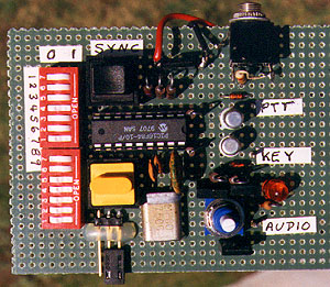
Homing In for April 1998 features complete construction plans for the Montreal Fox Controller, an engineering gift to radio-orienteering enthusiasts from Francois Tremblay VE2JX and Jacques Brodeur VE2EMM. The photo shows KØOV's prototype on perforated board. Etched circuit boards are available.
The Montreal Fox Controller features a 16F84 reprogrammable PIC with non-volatile flash memory. An inexpensive microprocessor crystal provides timing accuracy and synchronization through long foxhunts. The MCW output is a keyed tone to drive the mike input of a two-meter FM rig. The CW output is an open-collector pulldown for on-off keying of an A1 transmitter per IARU rules on 80-meter foxhunts.
MOx messages are sent in slow code, but station ID is sent at higher speed, to avoid hunters confusing the callsign with the fox number. You can put out your foxes in advance and have them come on automatically at hunt time. Delayed startup is programmed with dipswitches in 30-minute increments from zero to 3 and a half hours.
For the schematic diagram and construction/operation details of this project, see the April 1998 issue of 73 Magazine and the Montreal Fox Controller Page.
The following files for this project are available for FTP download at this site:
Update March 2000: Charles Scharlau NZØI writes:
"I just wanted to let you know that I have posted an English translation of Jacques Brodeur's original Fox Controller software on my web site. (This was done with Jacques' consent.) Both the comments and variable names have been translated. Actually, there are two flavors of this new software. One version is for international-style ARDF, and the other is adapted to ROCA-style hunts. I've built seven of Jacques' controllers, and I appreciate that they are so inexpensive. By adding a travel alarm clock automatic turn-on circuit to each controller, it is convenient to have all the transmitters come on the air simultaneously at just the right time."
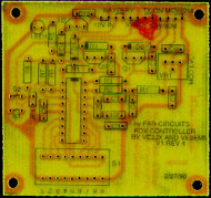
For simple onesy-twosy projects like this, my preference is to wire them up on perforated board, as in the illustration above. But for a full set of five international-style foxboxes, etched circuit boards will make the job go much faster. FAR Circuits of Dundee, IL is supplying blank circuit boards for this project. Price is $4.50 each plus $1.50 shipping for up to four boards. On standard 72 dots-per-inch monitors, the board photo below is actual size.
For those who like to make their own circuit boards, Jacques VE2EMM has this suggestion: "I now do my printed circuits directly on the copper with a modified HP7225 plotter. I modified the pen holder to take a Stadtler 313 permanent ink pen at a cost of CAN$1.39. This pen is better than the General Cement resist pens by an order of magnitude. It makes really nice printed circuits."
VE2EMM has laid out a board for this project in Easytrax for DOS format, which is freeware from Protel. To get the layout file, contact Jacques directly.
VE2EMM graciously offers to program your PICs for this project. Send your blank 16F84 ICs along with a self-addressed label and two dollars for return postage (US or Canadian currency, no checks please) to Jacques Brodeur, 5034 Joseph-A-Rodier, Montreal, Quebec, Canada H1K 5E1.
Station identification (callsign, six CW characters maximum) is held in non-volatile data memory. As pre-programmed by FOXBOX1.ASM, the unit identifies as "DE FOXBOX." Changing from "FOXBOX" to your own callsign is a simple field procedure.
--  MORSE ENCODING TABLE --

The program generates one morse character per BYTE, bitwise, LSB to MSB.

   0 = dit (switch closed)
   1 = dah (switch open)

The byte is shifted to the right bit by bit, until the
last 1 is left, this 1 is an END OF CHARACTER indicator.

   CODE  S1 SETTINGS    MSD  LSD    COMMENTS
           87654321     dec  dec
   ----    --------     ---  ---    --------------------
KN -.--.   00101101      2   13     Go only
SK ...-.-  01101000      5    8     Clear
AR .-.-.   00101010      2   10     Over, end of message
BT -...-   00110001      3    1     Pause
AS .-...   00100010      2    2     Wait, stand by
 / -..-.   00101001      2    9
 0 -----   00111111      3   15
 1 .----   00111110      3   14
 2 ..---   00111100      3   12
 3 ...--   00111000      3    8
 4 ....-   00110000      3    0
 5 .....   00100000      2    0
 6 -....   00100001      2    1
 7 --...   00100011      2    3
 8 ---..   00100111      2    7
 9 ----.   00101111      2   15
 A .-      00000110      0    6
 B -...    00010001      1    1
 C -.-.    00010101      1    5
 D -..     00001001      0    9
 E .       00000010      0    2
 F ..-.    00010100      1    4
 G --.     00001011      0   11
 H ....    00010000      1    0
 I ..      00000100      0    4
 J .---    00011110      1   14
 K -.-     00001101      0   13
 L .-..    00010010      1    2
 M --      00000111      0    7
 N -.      00000101      0    5
 O ---     00001111      0   15
 P .--.    00010110      1    6
 Q --.-    00011011      1   11
 R .-.     00001010      0   10
 S ...     00001000      0    8
 T -       00000011      0    3
 U ..-     00001100      0   12
 V ...-    00011000      1    8
 W .--     00001110      0   14
 X -..-    00011001      1    9
 Y -.--    00011101      1   13
 Z --..    00010011      1    3
 SPACE     00000000      0    0    Word space (special exception)
 EOM       11111111     15   15    End of message (special exception)
When Jumper JP1 is in place, the setting of the nine-section dipswitch selects startup delay, fox message and cycle rate. The dipswitches are read and acted upon when RESTART button is depressed.
Setting      Cycle         Message        Delay
 x,x,x      S1-9,8,7      S1-6,5,4      S1-3,2,1
 -----      --------      --------      --------
 0,0,0     Continuous        MO           None
 0,0,1     Continuous        MOE          0:30
 0,1,0     2 minutes         MOI          1:00
 0,1,1     3 minutes         MOS          1:30
 1,0,0     4 minutes         MOH          2:00
 1,0,1     5 minutes         MO5          2:30
 1,1,0     6 minutes         MON          3:00
 1,1,1     7 minutes         MOD          3:30
An automatic shutdown is included in the program to stop all transmissions after four hours and place the microprocessor in the "sleep" mode for very low battery drain. This feature is used in European hunts to signal the end of a practice session. It also prevents complete discharge of the fox batteries if the box isn't recovered immediately. Time-to-shutdown cannot be programmed in the field, but you can change the shutdown timer counter in the PIC program. In the source code file (FOXBOX1.ASM), look for the following line:
MOVLW D'24' ;HUNTING TIME IN 10 MINUTES STEPS
Modify the value as appropriate to change the duration of transmissions. Examples: "D'24'" (the default) gives 4 hours (240 minutes), "D'12'" gives 2 hours, "D'36'" gives six hours, and so forth. The modified FOXBOX1.ASM file must then be recompiled and the PIC must be reprogrammed.

 Back to the Foxboxes for Mobile and On-Foot Transmitter Hunts page
Back to the Complete index of Homing In columns
Back to the Homing In Radio Direction Finding home page
This page updated 7 May 2009