From my Homing In column in the February 1997 issue of 73 Amateur Radio magazine
Cubical quads are popular antennas for VHF and UHF radio direction finding (RDF) in many places around the country, including southern California. One reason why you see so many quads on vehicles at our hidden transmitter hunts (T-hunts) is that quads can easily match the polarization of the hidden signal. This can make the difference between success and failure in some cases.
Let's say that the signal you're tracking has horizontal polarization, but you are using a vertically polarized RDF system[1]. This cross-polarized condition means that the direct incoming signal is between 14 and 25 dB weaker in your receiver, reducing your effective RDF range. Worse yet, any signals from the hider that propagate to you by reflection from nearby buildings, intermediate hills, and distant mountains undergo a polarization shift. That makes them appear stronger, relative to the direct signal, than they would if your antenna had horizontal polarization. As a result, you might end up chasing reflected signals throughout the entire transmitter hunt, never getting accurate bearings on the direct signal.
With a simple slip joint at the boom-to-mast junction, a two-meter quad is easily changed from horizontal to vertical polarization or to any other linear polarization angle. By adjusting your quad's polarization to maximize signal strength at the start of each T-hunt, you can usually avoid the problems of hunting cross-polarized signals.
The slip joint method has a few drawbacks. Sometimes it's not easy to tell for sure what polarization the hider is using, so you must check again occasionally as you progress toward the T. That's not fun if you have to stop and get out in the rain. Sometimes there are several transmitters to be found with different apparent polarizations, requiring frequent changes. Wouldn't it be better to be able to make the selection quickly from inside your vehicle?
Crossed yagis have been successfully used by T-hunters for polarization agility. Back in April 1989, my Homing In column described the setup of the late Vince Stagnaro WA6DLQ, who put the elements of two KLM yagis on one boom with separate feedlines and a switchbox to select six polarization modes.
Many T-hunters, myself included, prefer quads to yagis because they are more compact. In most cases, a mobile-mounted quad provides a better RDF pattern than a mobile-mounted yagi of the same size. That led me to design and build a multiple-polarization RDF quad for T-hunting.
While separate driven elements for horizontal and vertical polarization on one quad could probably be made to work. But a more elegant solution would take advantage of the cubical quad's inherent symmetry, which makes all elements able to support both polarization modes simultaneously.
Let's go back to basics for a moment. AC currents at VHF frequencies in antennas behave differently from AC currents at 60 Hz in your house wiring. The quantity of electrons passing per second along the power cord of your toaster is the same at the plug end, the toaster end, and everywhere in between. But if you could measure the RF current at several points along the driven element (DE) of a quad antenna, you would find that it differs. This property makes the DE radiate signals from transmitters and capture signals for receivers.

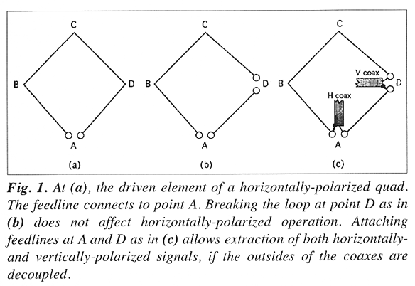
Figure 1(a) above shows a typical quad driven element loop. Circumference is one wavelength, about 80 inches at two meters. The feedline is connected to point A, which gives a horizontally polarized transmitted signal. Received signals of horizontal polarization induce currents in the loop that go down the feedline to the receiver. Vertically polarized signals induce currents within the loop also, but their magnitude and phases are such that they cancel out at point A.
RF current from the transmitter is highest at point A. There is another transmitting current maximum at point C. At points B and D, current is at a minimum. Theoretically in a perfect quad, loop current would be zero at these points. In a practical beam, it is less than 1 per cent of the maximum.
If there is indeed no current at point D, why couldn't we just break the loop there, as in Figure 1(b)? We can! If you have antenna analysis software such as EZNEC, try this as an "exercise for the reader." Insert a very high value resistive load in series at point D in the DE of your favorite diamond-shaped quad model for any band. If the quad is symmetrical, then the resonant frequency, pattern and feedpoint impedance will show very little change.
With the added break, we have the driven element of Figure 1(b). Feeding it at point A gives horizontal polarization, while feeding it at D gives vertical polarization. Both modes can be handled by the quad simultaneously. So why not just hook a feedline to each point and switch from one to another at the receiver, as in Figure 1(c)?
Whoa! Breaking the loop and adding a 50-ohm load at a current minimum will not affect it, but adding an unbalanced feedline certainly will. The braid of the coax will become part of the antenna. As another EZNEC exercise, hang a 6-foot wire (representing the coax shield) at a current null point in your favorite quad DE and watch the pattern change for the worse.
Fortunately, current flow on the outside of the coax can be choked off to restore the current minimum. A balanced-to-unbalanced transformer (balun) will do it. RF current will be confined to the coax inner conductor and the inside of the shield, and will remain near zero for cross-polarized signals. For the unused polarization mode, it is almost as if the coax isn't there at all!
VK5RN has documented a circularly-polarized quad for OSCAR satellite use that has two feedlines with sleeve baluns[2]. These devices, sometimes called bazookas, are made from thin-wall metal tubing of carefully selected diameters. I did not want a pair of bazookas on my T-hunt mobile quad because they are heavy and would add lots of asymmetrical windload at freeway speeds. Instead, I tried a choke made of ferrite beads. Measurements by W2DU[3] show that 25 beads of #43 ferrite material over a coax line provide 850 ohms impedance to currents on the outside of the shield at two meters.

One of the 50-bead baluns without the heat-shrink tubing.
I modified a Cubex Yellow Jacket four-element two-meter quad by installing a second feedline termination block. I found that Amidon FB-43-2401 beads have an inner diameter of 3/16 inch, so they fit nicely over the RG-58X low-loss feedlines after removal of the outer jacket. The two feedlines go down the 3/4-inch Schedule 40 PVC pipe mast to a two-position coax switch in the van, then to the receiver. Coaxes are exactly the same lengths to make it easier to achieve circular polarization, as will be shown later.
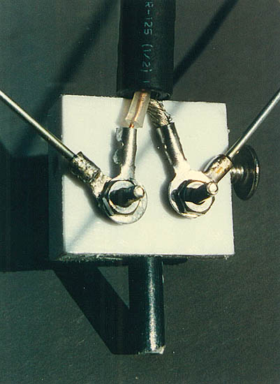
Close-up of a feedpoint block. The first bead fits over the point where coax shield and center conductor are separated.
At a local hilltop, I compared the new dual-polarization quad to an unmodified Cubex Yellow Jacket using a calibrated attenuator and signals from repeaters, local and distant. The results delighted me. The directional pattern of the dual-quad was just as good as that of the reference quad. Cross-polarized signals were attenuated 14 dB by the dual-quad, which represented about 3/4 scale on my receiver S-meter.
Forward gain of the dual-quad was about a half dB less than the stock Cubex quad, a negligible difference. Making the comparison was difficult, because when testing the stock quad, the S-meter would vary plus or minus 20 per cent as the feedline moved around inside the van, due to unwanted feedline signal pickup. On the other hand, outputs of the dual-quad were rock solid with feedline movement, thanks to decoupling by the ferrite baluns.
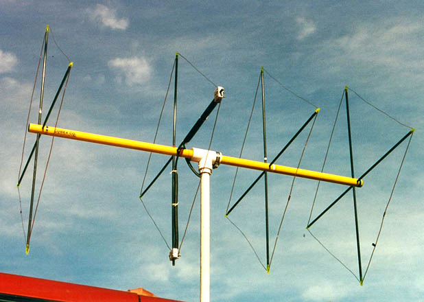
The dual-quad is ready for a hunt, mounted atop a rotatable PVC pipe mast that comes up through a hole in the van roof. Note that the feedlines pass over the top of the boom before going into the PVC pipe, but they do not wrap around for several turns as in stock Yellow Jacket quads.
About this time, a Saturday night mobile T-hunt was getting under way. This would give the quad a real workout. Paul Jaruszewski KD6LOR and Jim Smerdel KK6ME had put out three hidden T's, transmitting intermittently on 146.565 MHz. Only one was copyable when I left the hilltop. By switching between feedlines, it was easy to tell that this signal had horizontal polarization. After I had gone a few miles, I began to detect weak signals after each transmission from the strong T. I toggled the coax switch a few times and determined that the weak signals were stronger in the vertical mode.
I found the strong signal first. It was in KD6LOR's truck in a hilltop parking lot overlooking Mission Viejo. Sure enough, its transmitting antenna was a horizontally polarized quad. I then took on the other two T's, which clearly had vertical polarization. There was now a bit of overlap in the transmissions and it was nice to be able to switch polarization to minimize the signal from the horizontal T while hunting the others.
Before long, I had found both of the weaker T's. Each had a quarter-wavelength vertical whip antenna mounted on a surplus ammunition can. One was chained to the base of a high voltage power line transmission tower, while the other was in a park on a steep hillside overlooking Lake Forest. This hunt was enough to convince me that a polarization-agile quad would be my new "weapon of choice" for future two-meter hunts.
Although gain and pattern of the test quad proved to be excellent, SWR was over 2.5:1. Upon further testing, I found that the DE was resonant at about 141.5 MHz. Apparently the pigtails between the ends of the bead baluns and the feedline blocks add to the DE's resonant length. I shortened the DE wires, which improved SWR but caused the pattern's back lobe to worsen. After some experimentation, I found that moving the reflector four inches closer to the DE made the SWR even better and minimized the back lobe.
SWR is now 1.6:1 for both polarizations. This is fine for receiving, because the feedline is decoupled well. Your receiver probably does not have exactly 50 ohms input impedance anyway. I also tried 50 beads per balun instead of 25. This increased cross-polarized signal rejection from 14 to 17 dB.
Your favorite two-meter corner-fed no-gamma diamond quad design should be suitable for use with this dual-polarization feed technique. Baluns of 25 beads each are inexpensive and adequate for RDF. You will need to strip the jacket from the coax for the beads to fit. Do not strip or comb the shield braid under the beads. If your coax diameter is so small that the beads will go over the jacket, it is not standard RG-58/U and not recommended for VHF.
Cover each balun with heat-shrink tubing and add a dollop of hot glue or other sealant at the ends before shrinking to keep water out. Keep the shield and center conductor leads from balun to feed block very short because they add to the DE resonant length. These pigtails are just 3/4 inch each on my quad, compared to 1-1/2 inches in the Cubex instructions.
As a check of your dual-feed quad's construction, try transmitting on two meters into one feedline with the other terminated by a wattmeter and a good VHF dummy load. Very little RF should leak from coax to coax. In my case, transmitting 22 watts into the horizontal coax gave only 6 milliwatts out of the vertical coax, and vice versa (35 dB isolation).
Wire lengths of the DE on my modified Yellow Jacket are 18-3/4 inches for the wire between the two feed blocks (measured screw-to-screw) and 59-3/8 inches for the wire that forms the other three sides of the loop. Lengths of the other Cubex element wires are unchanged. Cubex instructions call for six turns of feedline around the Yellow Jacket boom, but these added turns are unnecessary and undesirable when the ferrite baluns are in place.
Hiders occasionally transmit unusual polarizations. For instance, an ammunition can T propped up in a tree may put out a signal polarized at a 45-degree angle between horizontal and vertical. There have even been some circularly polarized T's to find on our Saturday night hunts.
By combining signals from the horizontal and vertical feedlines of the dual-quad with proper phase relationship, you can achieve 45-degree and circular polarizations. My Homing In column for April 1989 has plans for WA6DLQ's 6-position polarization switchbox. Though intended for use with his dual-feed yagi, it will also work with the dual-quad. A similar switchbox is in some editions of the Radio Society of Great Britain's VHF/UHF Manual. Feedlines from switchbox to each feedpoint must be exactly equal lengths when using the switchbox.
If T-hunting in your area requires you to make frequent polarization decisions, consider adding a dual-polarization quad to your bag of tricks. When Ed Buchanan owned Cubex, he agreed to sell a dual-feed version of the Yellow Jacket quad to Homing In readers. It included two feedpoint termination blocks and associated hardware. Ask the new owners of Cubex if the "T-hunt Special" is still available.
Whether you make your own dual-polarization RDF quad or try the modified Cubex Yellow Jacket, please let me know how it works for you.
--------------------
NOTES:
[1] Dopplers, switched-pattern and time-difference-of-arrival RDF sets use vertically polarized dipoles or ground plane antennas.
[2] Robertson, "The Quadraquad--Circular Polarization the Easy Way," QST Magazine, April 1984, page 16.
[3] Maxwell, "Some Aspects of the Balun Problem," QST Magazine, March 1983, page 38. Ferrite baluns are also briefly described in recent editions of The ARRL Handbook.
© 1997 and 2009 Joseph D. Moell. All rights reserved.
 Back to the Southern California Style Transmitter Hunting page
Back to the Homing In home page
This page updated 15 June 2024