Yes, It's Truly a Doppler
The first article in this Homing In column series took you on a journey that started with Christian Doppler's birth over two centuries ago. While trying to understand color changes in double stars, this astronomer/physicist was the first to document the apparent frequency shift of waves when source and observer are in relative motion. Doppler radio direction finding (RDF) sets for ham radio came along in 1978, adapted from a spinning antenna scheme that was first proposed just after the Second World War. This time, in Part 2, we'll clear up some misconceptions about antennas that produce Doppler shift without physical motion.
by Joe Moell KØOV
In a typical VHF/UHF Doppler RDF antenna unit, three or more whips or vertical dipoles are equally spaced along the circumference of an imaginary horizontal circle. An electronic switch connects them to the receiver one at a time in sequence, for equal periods of time. This simulates a single whip moving along the imaginary circle at a physically impossible high rate of speed, sufficient to provide periodic Doppler frequency shifts in all incoming signals.
Many hams confuse the rotation frequency, the Doppler tone frequency, and the tone's frequency deviation, all of which are stated in Hertz (Hz). The array rotation rate (number of times that each whip is sequenced on in a second) is always the same as the fundamental frequency of the induced Doppler tone. Typical rotation rates range from 300 to 1000 Hz, corresponding to the audio passband of narrowband FM voice receivers. Higher rates are avoided because they produce audio harmonics that may be interpreted as noise by the receiver's squelch circuit.
Peak FM deviation of the Doppler tone is given by the formula in Figure 1 below. For best performance, deviation must be high enough that the tone can be easily detected and its phase determined when the signal isn't full-quieting and when voice or other modulation is present. A 4-element set with whips in an 18-inch square, switched at 500 revolutions per second, produces peak Doppler tone deviation of about 0.5 KHz.

Figure 1. As a vertical antenna element moves rapidly on a circular track, the Doppler shift imposes an FM tone on received signals. Peak FM deviation of the tone (S in Hz) is a function of signal frequency (Fc in MHz), circular rotation rate (Fr in Hz), and radius of the circular track (R in inches), according to the formula.
The bottom of Figure 1 illustrates the sinusoidal waveform that would be produced in an FM receiver discriminator by a single moving vertical antenna. Figure 2 below is an oscilloscope trace of the audio output of the FM receiver in a typical four-whip Doppler setup. Signal wavefront phase changes that are presented to the receiver as the antenna elements are sequentially switched show up here as periodic pulses. All of the information necessary to determine signal bearing is contained in the amplitude, polarity and timing of these pulses. The rise and fall slopes of the pulses and the "tilt" between them are functions of the frequency response of the audio stages, and are inconsequential. Note the large pulses of opposite polarity when switching to antennas #1 and #3, and the very small jumps at #2 and #4. From this, we can tell that the incoming signal direction is approximately perpendicular to an imaginary line through antennas #1 and #2.
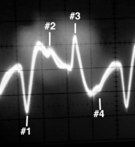
Figure 2. Audio output waveform of a receiver with a typical 4-whip Doppler set in operation.
A frequency domain analysis of the audio of Figure 2 looks like Figure 3 below. The fundamental frequency (474 Hz in this case, same as the rotation rate) is the only component of interest for bearing determination. The array of harmonics comes about because of the switching steps of the audio. If you have encountered Fourier series in a math class, you'll recognize the characteristic decreasing harmonic values. Note that only odd-numbered harmonics are present (1422 Hz, 2370 Hz, 3318 Hz and so forth). Changing the number of evenly-spaced whips will change the relative levels of the odd harmonics, but will not add any even harmonics to the tone spectrum. This is important, as we will see in a later installment of this series.
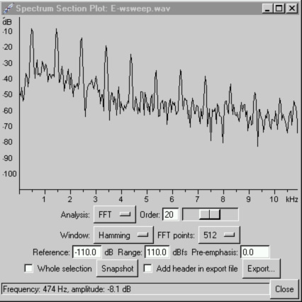
Figure 3. Frequency components in the audio output of a typical 4-whip Doppler.
In a practical Doppler set, a very narrow audio bandpass filter (as low as 2 Hz bandwidth) is synchronized to the antenna rotation rate. Because it is locked to the fundamental frequency of the Fourier series, this filter strips out the upper harmonics as well as the unwanted noise and modulation on the incoming signal. The output is a sine wave (like Figure 1) with just the RDF information we want (relative phase) on it. It's nearly indistinguishable from what would be achieved with an infinite number of whips, which explains why it's possible to have high bearing accuracy with just three or four whip antennas.
Just Like the Movies
Despite the above explanation and the good performance of Doppler RDF sets, some hams have trouble accepting the concept of a few sequenced vertical antennas taking the place of a single vertical antenna moving in a circular pattern. This was the topic of considerable debate on an Internet discussion group for transmitter hunters. Some writers claimed that it is impossible for switched verticals to produce "true Doppler" response. But no matter what you choose to call them, they do indeed follow Doppler's principle and the equations derived from it.
For those having trouble thinking this through, I suggested an intermediate step. Consider the theoretical case of an infinite number of individual whips and a perfect switching system in place of the single moving whip. This is the same piecewise approximation technique used in the calculus. There are tiny phase steps added to the received signal every time the switch operates, creating an infinite-step sinusoidal Doppler-induced carrier shift in the receiver discriminator output, identical to the physically rotating whip case. Doppler's frequency shift prediction still exactly describes the frequency changes that the receiver perceives.
Now reduce the number of whips from infinity to a practical number. This reduces the number of pieces in the piecewise approximation of one rotation from infinity to the number of whips. The receiver's discriminator output still includes phase jumps corresponding to antenna switching steps, but they are fewer in number and greater in amplitude. The phase information necessary to determine our RDF bearing is still present in the fundamental frequency term of this series. The harmonic content is greater and more filtering is required than in a million-whip array, but our narrow bandpass filter strips all the harmonics out.
Some members of the Internet discussion group were still troubled about all the simulated antenna movement being encoded in very brief phase jumps, while the rest of the time one antenna is connected to the receiver. But the important thing to remember is that it's the combination of both the jumps and plateaus (switching and sitting times) that simulates the motion. When you watch a movie, you are seeing a series of still photos (frames) that snap from one to another with rapid transitions. It is the combination of transitions and still frames that the viewer perceives as smooth motion. The eye and brain act as a filter, just as the filtering in the Doppler set. If you were to eliminate either the still frames or the transitions, then the simulation of smooth motion on the screen would be lost. Similarly, the combination of both the phase steps and the plateaus in between creates the waveform that the narrowband filter uses to extract the Doppler data with high accuracy.
With this explanation, almost everyone in the group was convinced. Then one writer pointed out that the peak amplitudes of phase jumps in the receiver output are not affected by the array rotation rate. Amplitudes remain the same because the phase steps are a function of the number of elements and direction of signal only. They remain the same number of electrical degrees when the rate changes. This appears contrary to the Doppler equation of Figure 1, from which increasing the rotation rate (Fr) should always cause increases in the deviation amplitude (S). Does that mean that it isn't a true Doppler after all?
This writer's incorrect conclusion came about because he confused phase modulation (PM) with frequency modulation (FM). They are similar forms of angular modulation, related mathematically but not identical. An FM signal's deviation is a function of only the amplitude of its modulating waveform, and is independent of the modulation frequency. PM deviation is a function of both the amplitude and frequency of the modulating waveform. In PM, the higher the modulating wave's amplitude and/or frequency, the greater the deviation.
A quick bit of history: In 1936, before phase-locked loops and other modern direct-FM producing techniques, it wasn't possible to achieve distortion-free high deviation in stable oscillators. So Edwin Armstrong invented an indirect method of transmitting VHF-FM. A crystal oscillator was followed by a "serrasoid" phase modulator, then by several doubler and tripler stages that also conveniently multiplied the deviation.
Armstrong's method directly varied the phase of the RF signal, which indirectly varied the frequency. By shaping the audio to be transmitted prior to applying it to the phase modulation stage (increasing the levels of low frequencies at a 6 dB per octave slope), his transmitter's output was indistinguishable from that of a direct-FM transmitter. Phase modulators with audio processing to achieve FM were standard for many years. These circuits were in the transmitter of the FM broadcast station that I tended in my college years and in the VHF/UHF business-band rigs that we converted to ham frequencies back then.
If we increase the switching speed of a Doppler array, the phase changes and thus the voltage peaks in the discriminator output do indeed remain the same for each jump in a cycle of rotation. The induced PM level on the signal has not changed. But since we have increased the rotation frequency and hence increased the frequency of all tone components coming out of the discriminator, the equivalent FM signal being detected does indeed have proportionally greater deviation. So the Doppler equation is indeed being followed, and we do have a true Doppler RDF set after all.
How Many Whips?
No matter how many vertical elements in your Doppler array, the adjacent elements along the rotation circle must not be more than 1/2 free-space wavelength apart, to avoid ambiguous bearings due to phase steps of greater than 180 degrees. Furthermore, adjacent element spacings of greater than 1/4 wavelength will produce phase steps of more than 90 degrees, lowering the level of the recovered audio tone and worsening the signal-to-noise ratio. With that in mind, the optimum spacing for a 4-whip "square" mobile array for VHF or UHF is slightly less than 1/4 wavelength on a side at the highest frequency to be used. For two meters, that is about 18 inches on a side.
Would eight elements be an improvement? It would reduce the harmonic content of the recovered Doppler tone, but that wouldn't be noticed with a good 2 Hz bandpass filter. More whips in the same size array would mean closer spacing and thus more RF coupling between them. That would be detrimental to performance in areas of high signal reflections, as we'll see in a future installment. So in practice, the difference in performance between 4-whip and 8-whip Dopplers of the same array size usually isn't significant.
On the other hand, for a fixed installation such as your home rooftop where plenty of space is available, or for a car-top array at UHF or microwaves, the added complexity of more elements in a larger array allows you to improve performance by increasing the overall array size (aperture). Consider a two-meter 8-whip array in an octagon pattern of 18 inches per side (i.e. the same adjacent whip spacing as the typical 4-whip Doppler for that band). Radius of rotation is more than double that of the 4-whip set, giving over 1 KHz Doppler tone deviation at the same rotation rate. The array aperture is more than doubled, which improves performance in multipath.
The downside is that this array has a diameter of almost 4-1/2 feet, so it won't fit on most vehicles. Furthermore, you would need 7-1/2 feet total diameter to provide ground plane under the whips. But a similar size (in wavelengths) array for the 70 cm band (440 MHz) would be only 2-1/2 feet diameter, which is practical.
A final caution: The equal spacing of elements along the imaginary circle of movement is critical. A 4-whip array must form a perfect square; an 8-whip array must form a perfect octagon, and so forth. Any error in element placement can cause significant bearing errors at some angles. If you use magnetic-mounts instead of a single fixed array-on-a-plate, be sure to use a template or make careful measurements when putting the mag-mounts on top of your vehicle.
That's enough theory for this time. In the next installment, I'll delve into practical Doppler antenna switching schemes. There are lots of circuits out there and some work much better than others. I'll explain why and describe some simple things you can do that may improve the performance of the one you're using now.
 Text and photos © 2003 and 2025 Joseph D. Moell. All rights reserved.
 Go to
Doppler Series, Part 3
Go to
Doppler Series, Part 3
Back to
Doppler Series, Part 1
Back to the Homing In home page
This page updated 24 April 2025